The Midi Maestro (MM) is great, I have it working nicely with my pedal board and even with Bluetooth to my tablet. However, those button clicks, whilst fine in a band setting, are too loud in an acoustic environment.
So, I took mine apart to see if the switches could be changed. They are surface mount push switches that are operated by a sprung button. Which means they could be changed but it would involve soldering, fly leads and risking damage to the Printed Circuit Board (PCB). The overall effect would not look nice and I would lose those nice mushroom buttons.
I decided to see what could be done with the minimum of change. My first attempt involved filling the voids inside the MM to reduce the reverberation of the click. While this helped somewhat, the clicks were still audible.
I then looked at the buttons to see why they were so noisy. I noticed that if I operated the buttons with my finger that they had a quiet operation, it was only when pushed by the sprung buttons that they made so much noise. I spent a while trialling methods to reduce the click effect. I used small Lego pieces, to see if would change the switch dynamics, this didn’t really work. I made buffer pads from aluminium tape, varying the thickness until I got a noticeable reduction in switch noise, this seems to work but they would not stay in place.
Spurred on by my success I tried variations of the shape of aluminium tape to see if they could be secured in place. I found a working design, but it was clunky and time consuming to produce and didn’t look very nice. It was then I noticed the MM rubber feet. They looked like suitable candidates for more experimentation.
I found that by placing the rubber feet over the switches, the button pressure is distributed over a wider area, simulating a finger press, which makes the switch operation quiet. The adhesive keeps the rubber feet on the switch, without bonding the switch in the down position, so they stay in place. The springs on the push buttons need to be removed, as the gap is now reduced and they will force the button down. This removal of the spring causes a change in feel of the operation, effectively replacing the spring (plush feel) with an elastomeric operation (calculator button feel).
In summary, using suitable rubber adhesive feet, I have finally found a modification that is reversible, works well, is easy to implement and cheap. The switches feel a little different, but you won’t be able to tell when using your foot. I can’t say how robust this modification is, but it seems to be holding up for me so far.
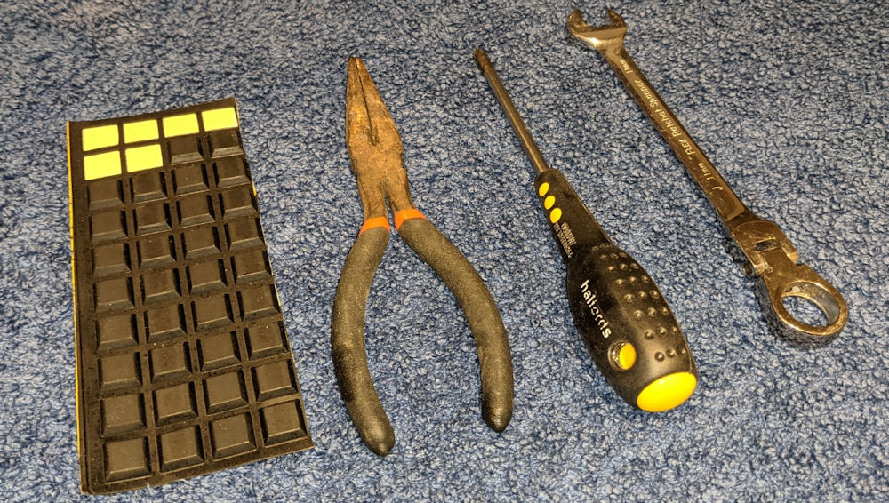
What you need:
-
Posidrive screwdriver (using a magnet makes it easier)
-
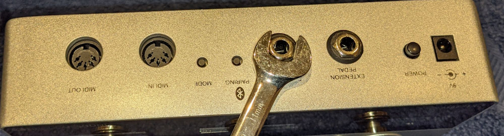
11mm socket or Adjustable Spanner
-
Small pliers
-
6 of 12x12x3mm square adhesive rubber feet
Steps: -
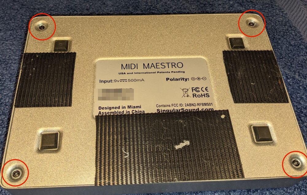
Remove the 4 screws securing the base plate, then remove the base plate.
-
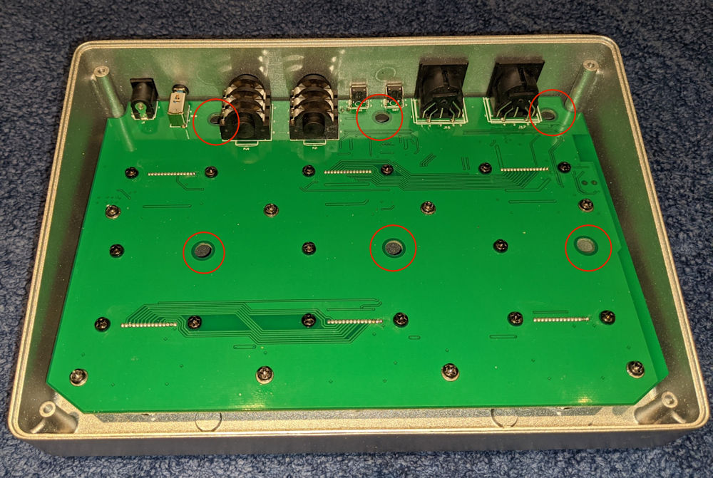
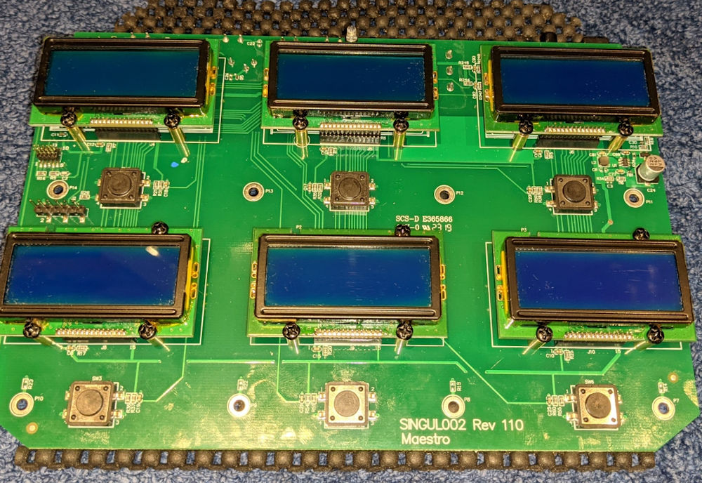
On the PCB there are 6 holes, through the holes are 6 screws securing the liquid crystal displays (LCD) to the front, these must be removed, they are a different size to the other screws so make sure they are kept separated.
-
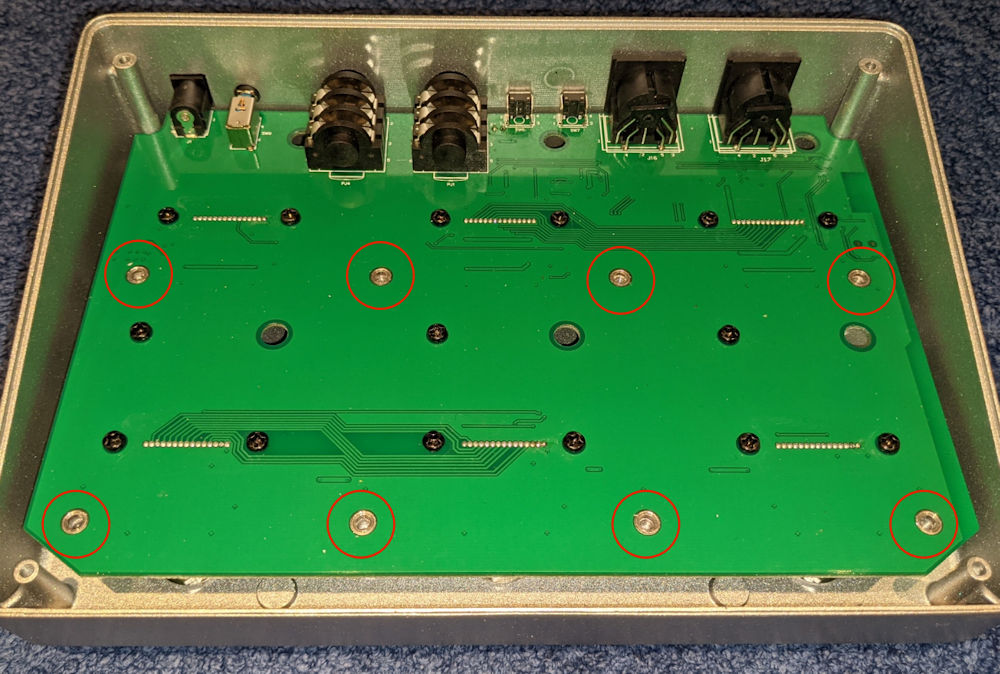
There are 8 screws securing the PCB to the front, they have silver rings (PCB pads) around them, do not remove the other screws as these keep the LCDs secured to the PCB.
-
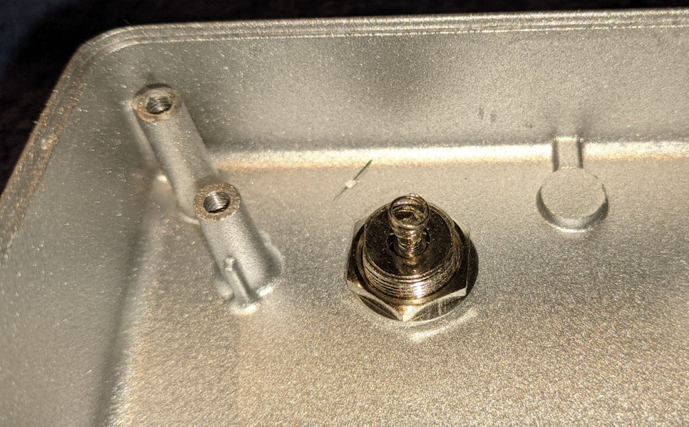
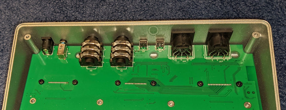
Using a spanner remove the 2 jack socket nuts and plastic washers.
-
The PCB can now be pulled gently forward and then lifted out of the chassis.
-
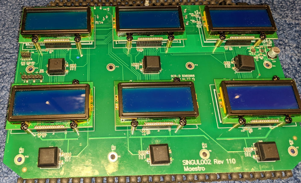
On each of the push buttons mounted to the chassis is an activation spring, they will need to be removed.
Push the button fully down and grab as much of the spring as you can with small pliers. The springs will pull off the switch with a firm twist and pull motion. Keep in a safe place so you can reverse the modification.
-
Take the 6 adhesive rubber feet and place them squarely over the switches, press down firmly so the adhesive bonds with the switch tops. Once on, press the rubber foot to make sure the button operation can be felt, it will be hard to hear.
The feet will rotate freely after installation, this has no effect on operation.
-
Gently install the PCB into the chassis, ensure all the sockets and switches locate on the rear holes.
-
Install the 8 PCB screws
-
Install the 2 jack socket nuts and washers
-
Install the 6 LCD screws through the PCB holes, if you drop one they will shake free, so don’t fret.
-
Make sure the switches operate correctly using the mushroom button, the click will be hard to hear now, but you will feel it.
-
Install the base plate and 4 screws.
-
Power on and check all the switches work electrically.


That’s it, enjoy your quiet Midi Maestro, your warranty is now void!