Hi all,
I shared this mouse hack for Beatbuddy control knob and noticed many of you were interested to know how it was done.
(May be not much here but in other forum and pages)
Initial Video link here:

This Hack is purely wiring connections. There is no software, no programming nor connecting to the computer/PC.
(Basically I am just duplicating the rotary encoder to the existing mouse roller and its left/right click buttons).
Below is a pictorial step by step procedure explained which will help you make one for yourselves.
Please be advised this will VOID the warranty and perform with care.
Here we go:
-
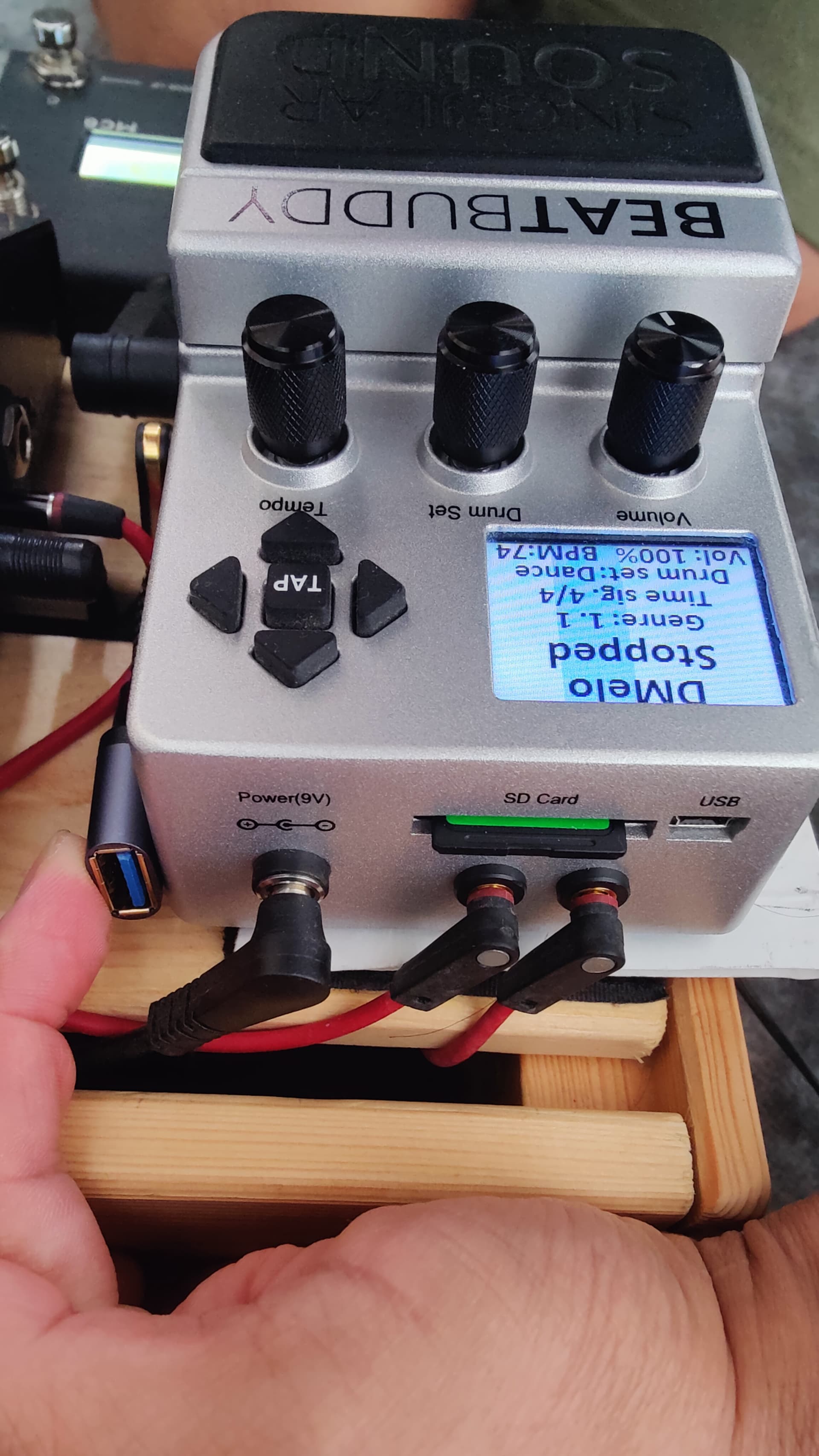
First take off the control knob caps x 2 for the ones which are labelled DRUMSET and TEMPO on your Beatbuddy. They should just pull out. Pic 1
-
Undo the hex nuts x2 that’s securing these shafts. The two shafts will then dangle freely within.
-
Now, Open the black plate of beatbuddy.
-
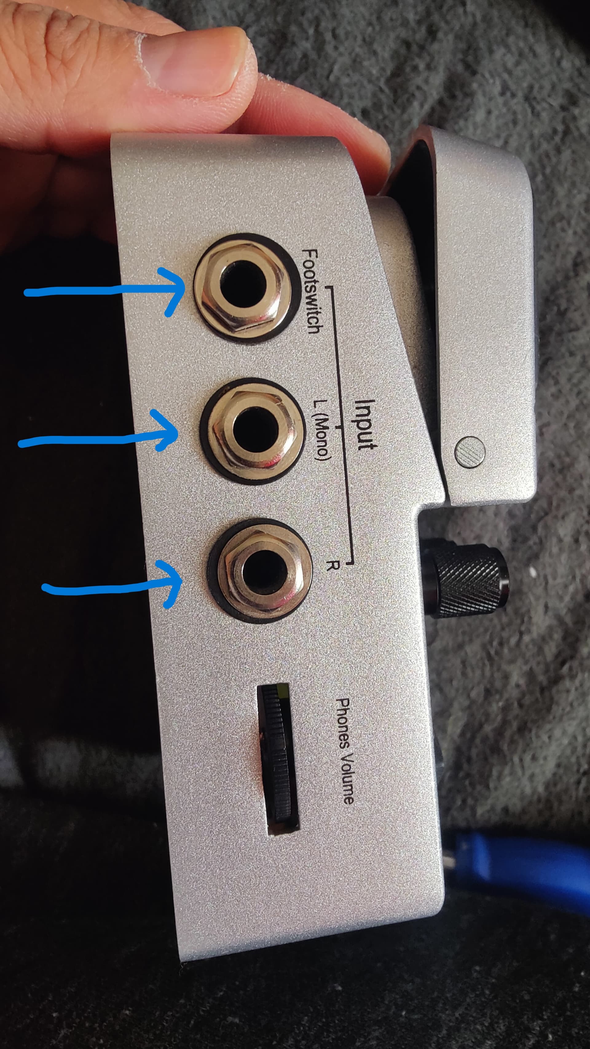
Loosen all external nuts that’s holding the input and output jacks including the headphone out jack nut. Pic 2 and Pic 3
-
Disconnect the red cable connector connecting the main switch. Pic 4
-
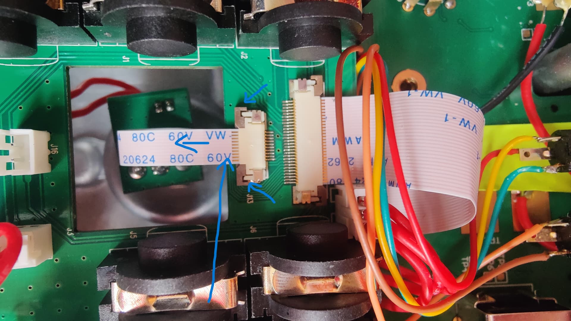
Disconnect the white flat ribbon ( Small one amongst the two white ribbons) that connects the control knobs and the board. This will make things easier. Pic 5
-
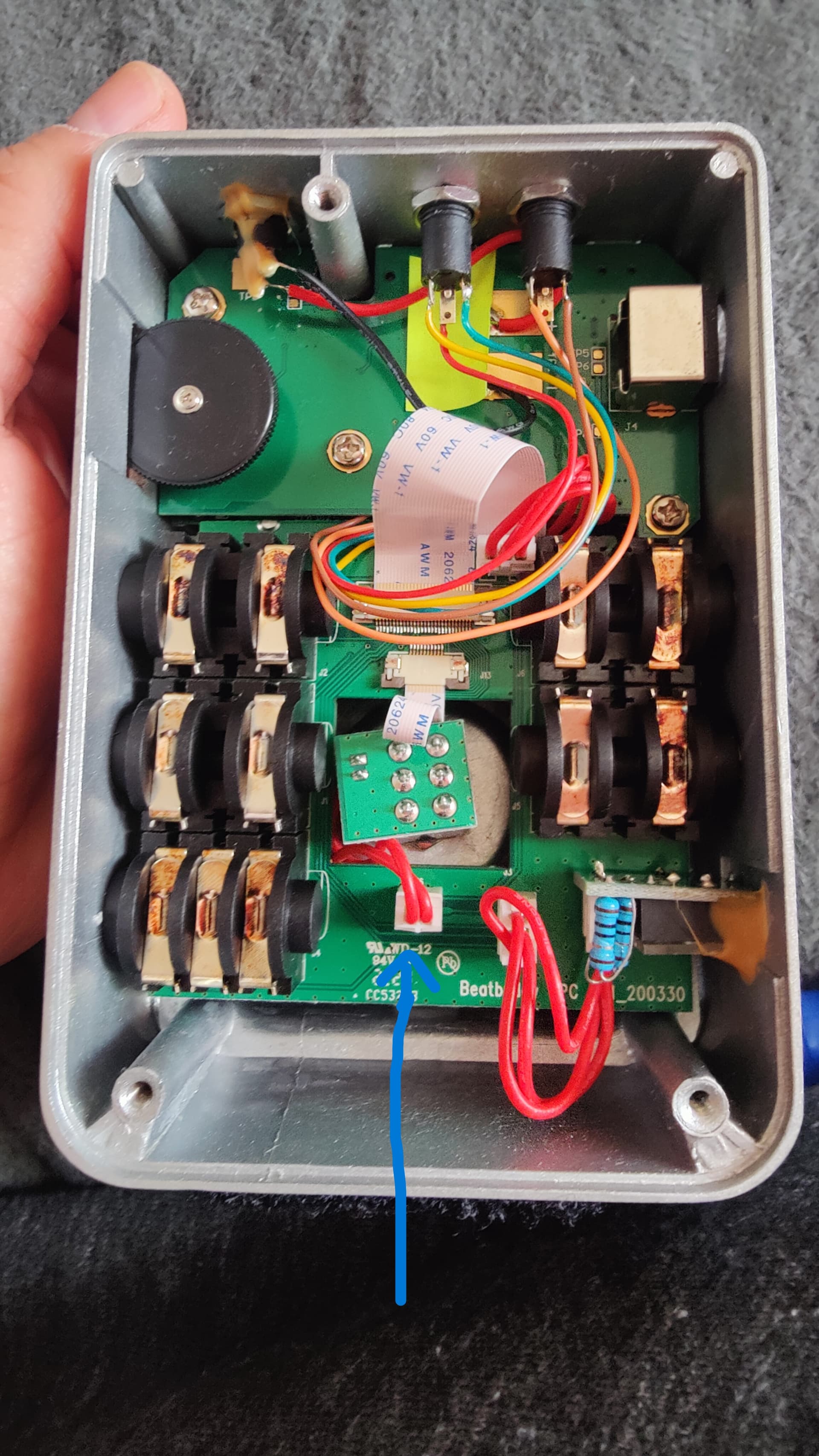
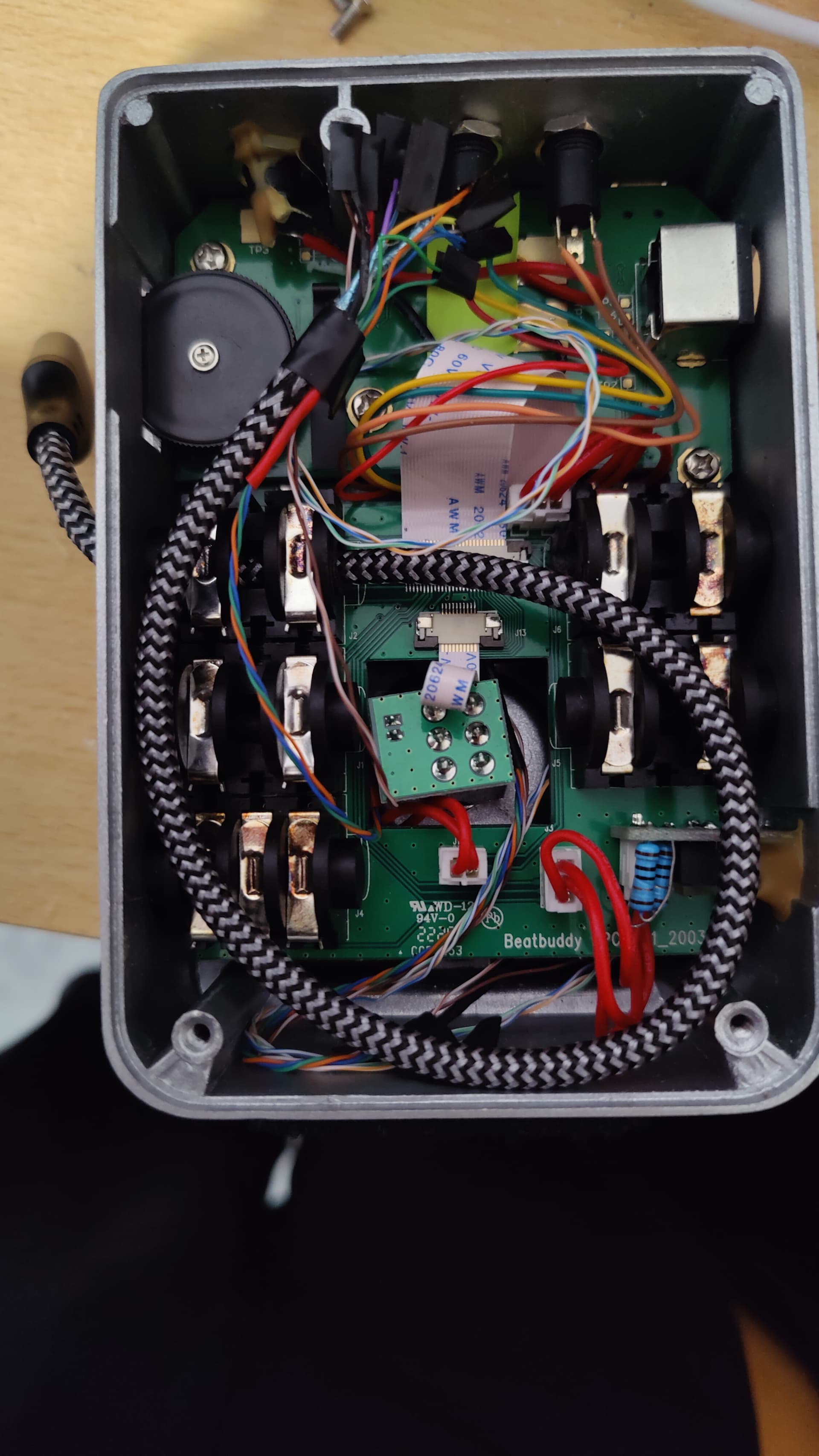
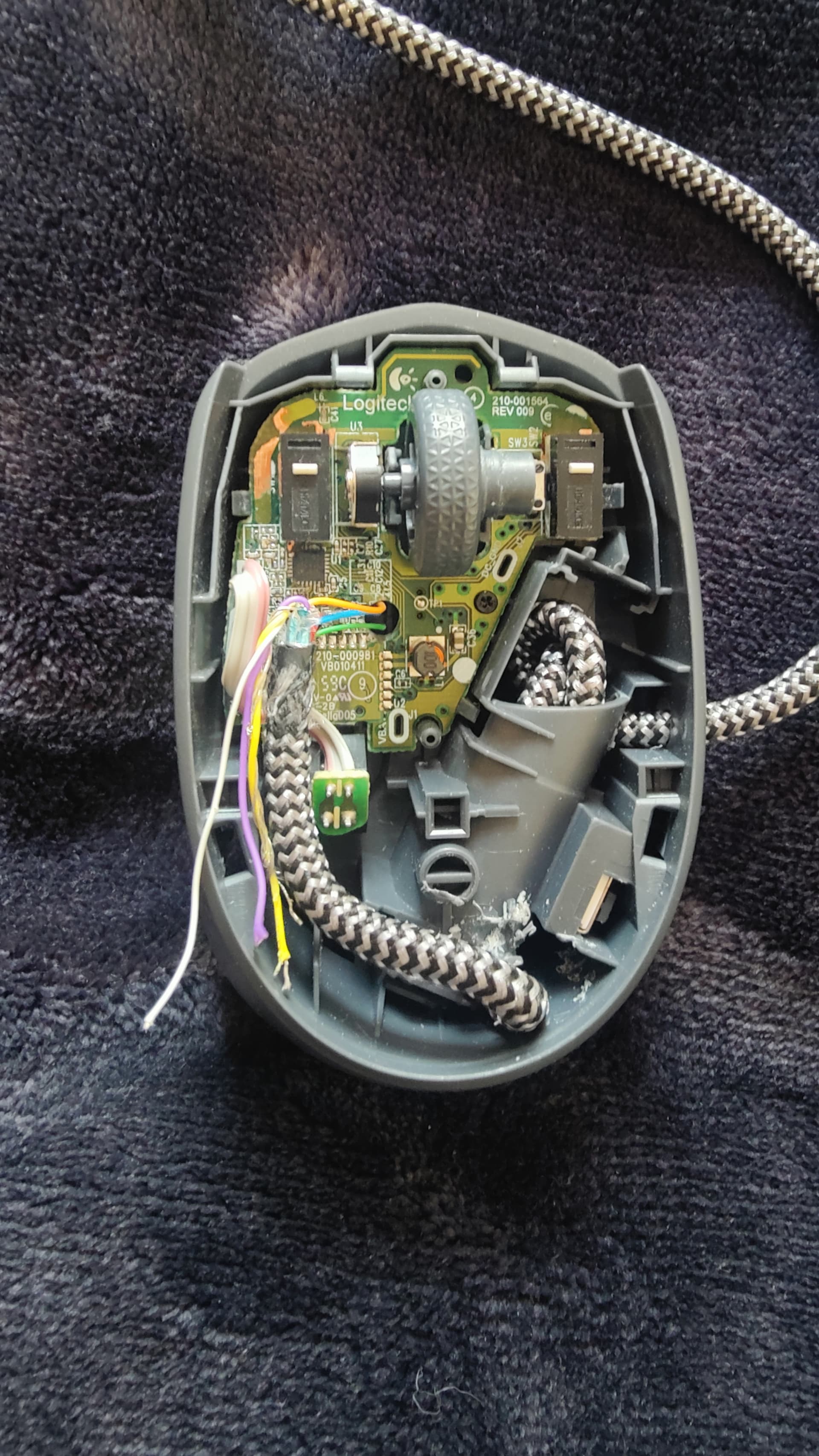
This board will now lift up. Lift it up about 5cms to access and take out the smaller PCB board which is located underneath. Pic 6
-
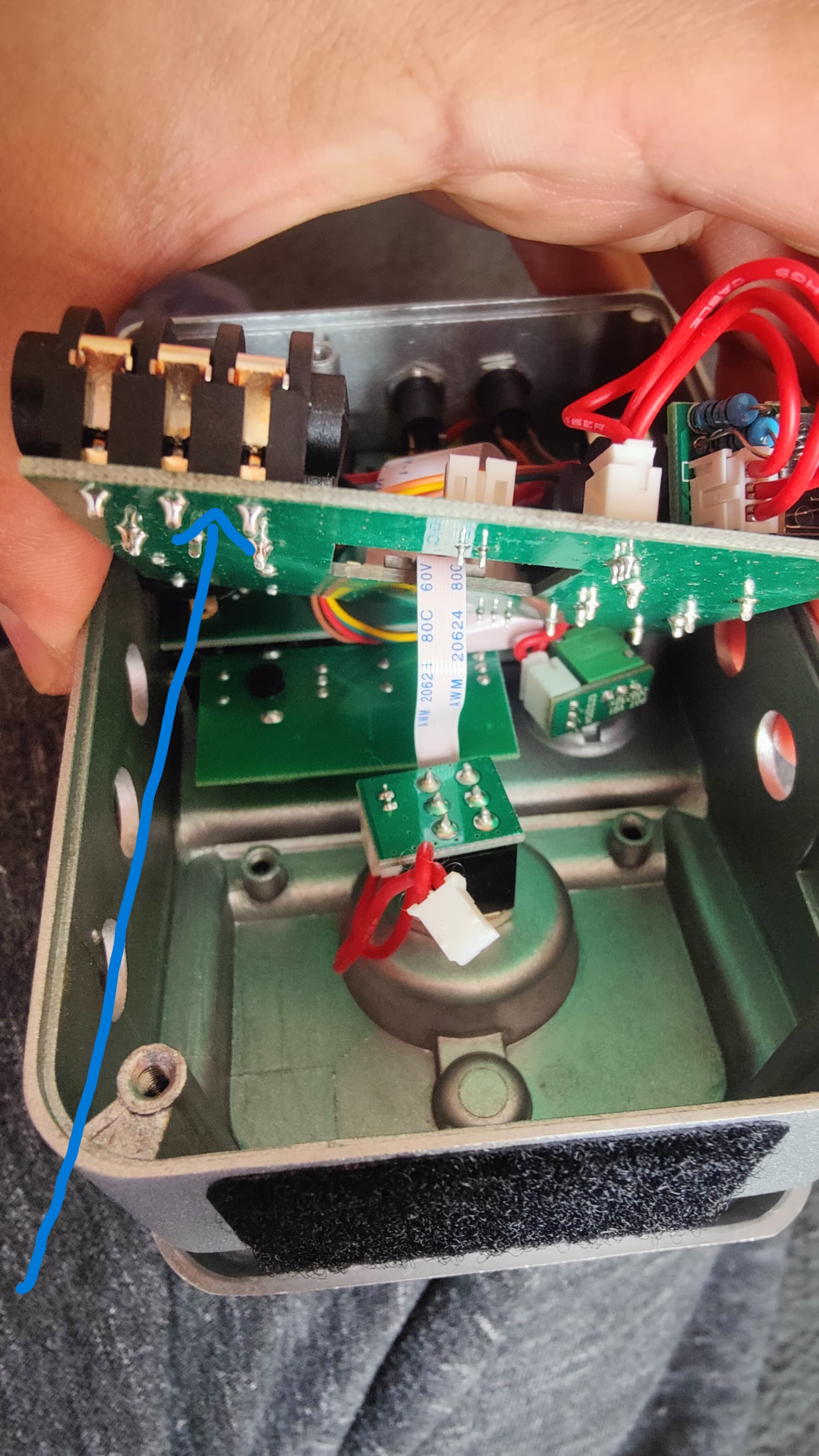
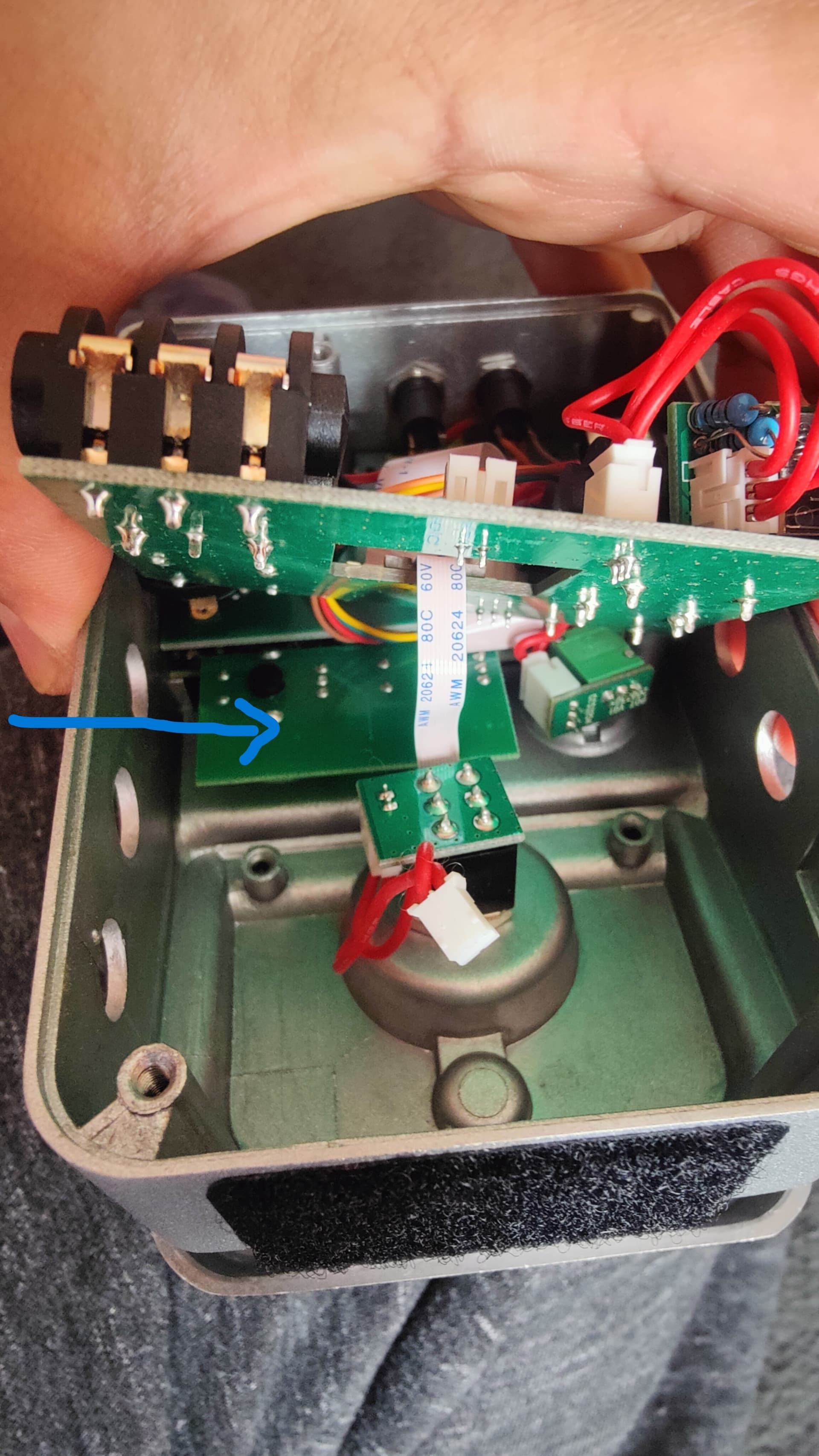
This small PCB board is where the previously loosen control shafts (Rotary Encoders- DRUMSET and TEMPO) are installed. Take this PCB completely out of the unit to work on. If this board is catching any other board, please gently loosen them too. Pic 7 Pic 8
-
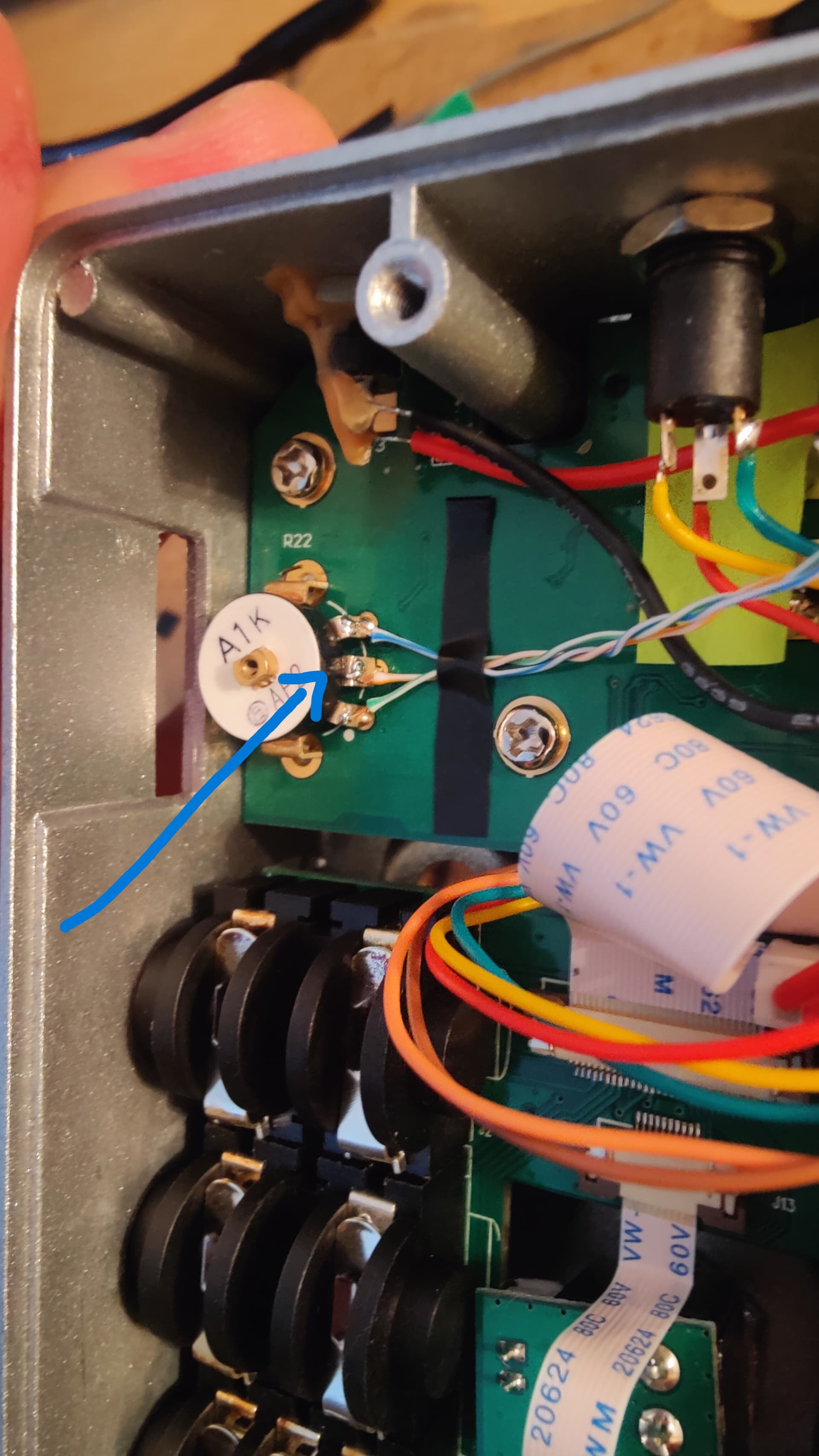
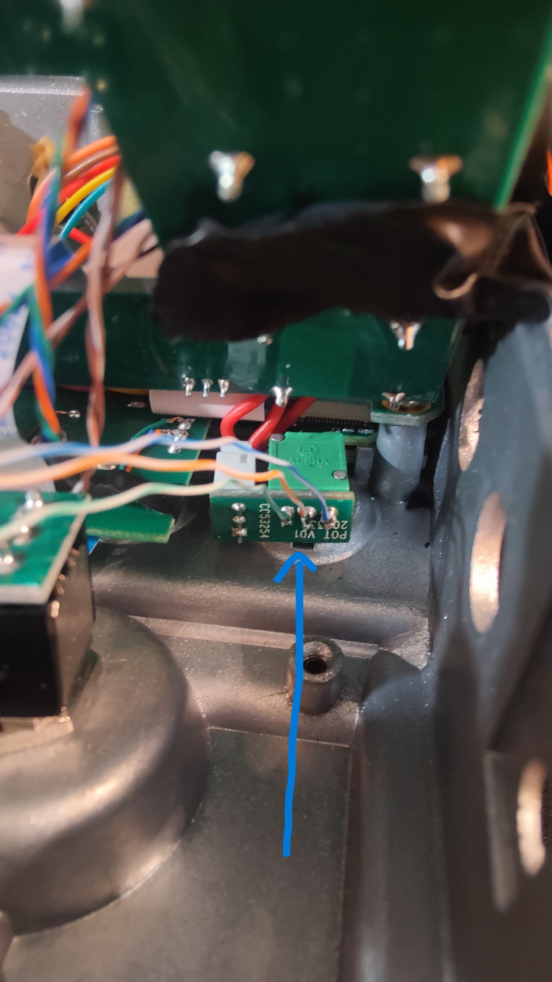
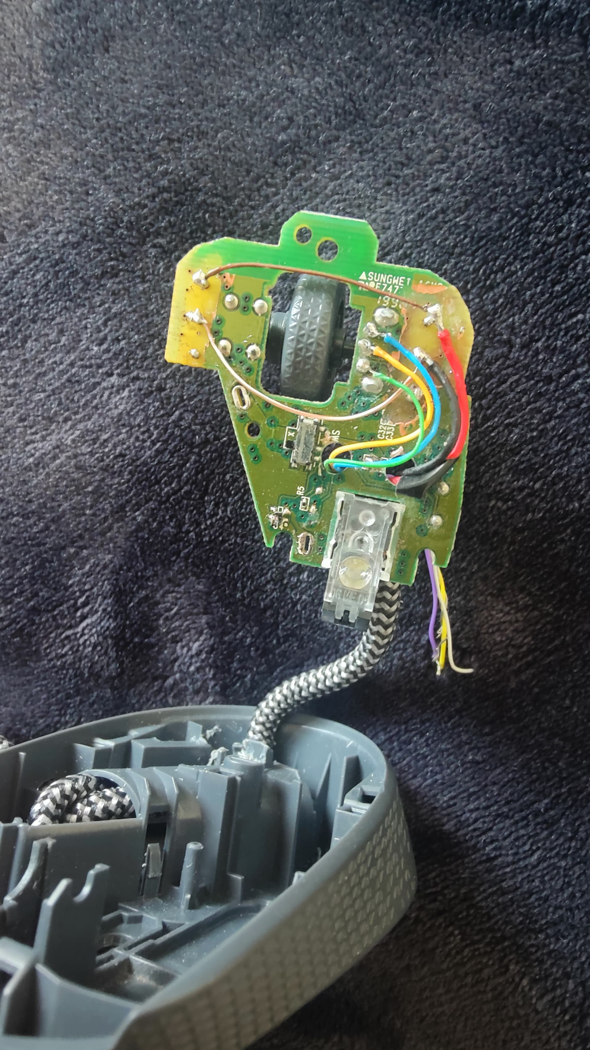
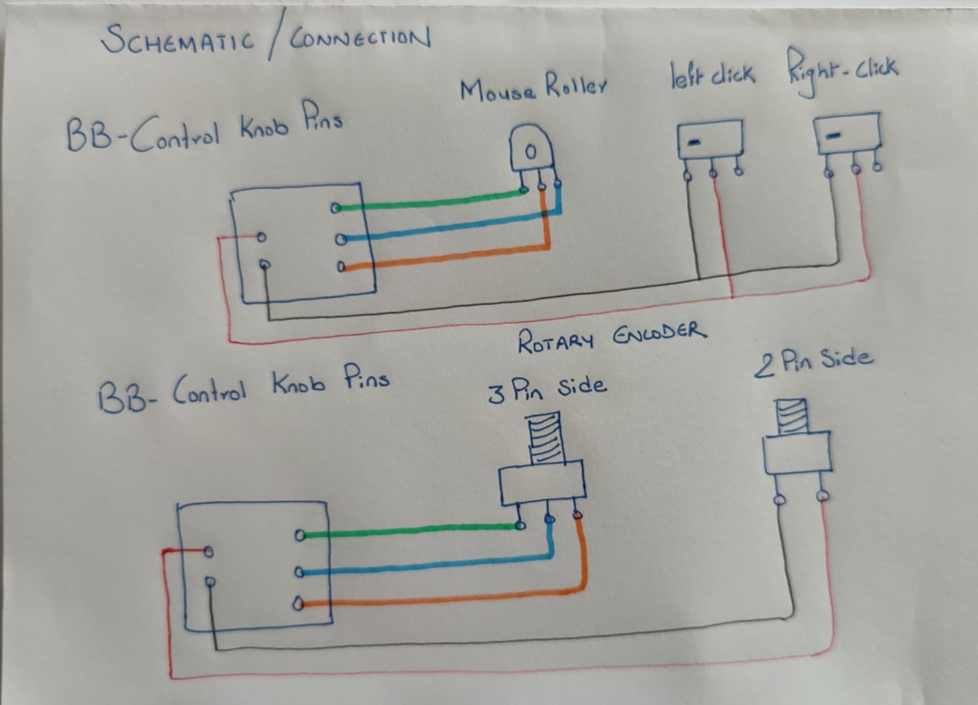
Now this is the board where you wanna make connections onto. Under this little board, you can see there are many soldered pins/legs of those Two Rotary Encoders.
-
Solder gently and make 5 individual wire connections to the 2+3 pins on the black dotted side of the board as shown in the photo. This side is where the encoder is installed for the main control/song selection/scroll knob. Pic 9

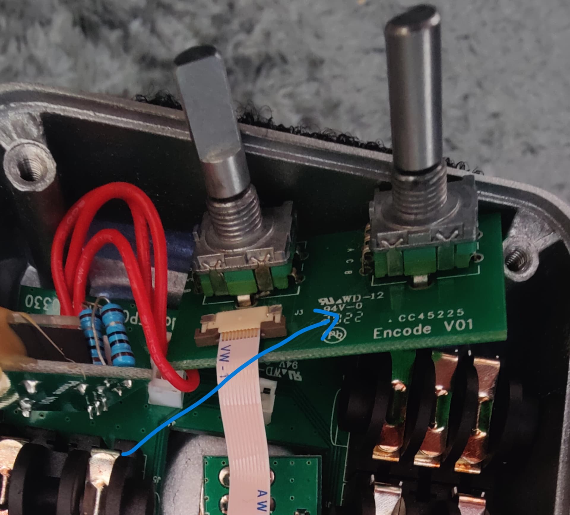
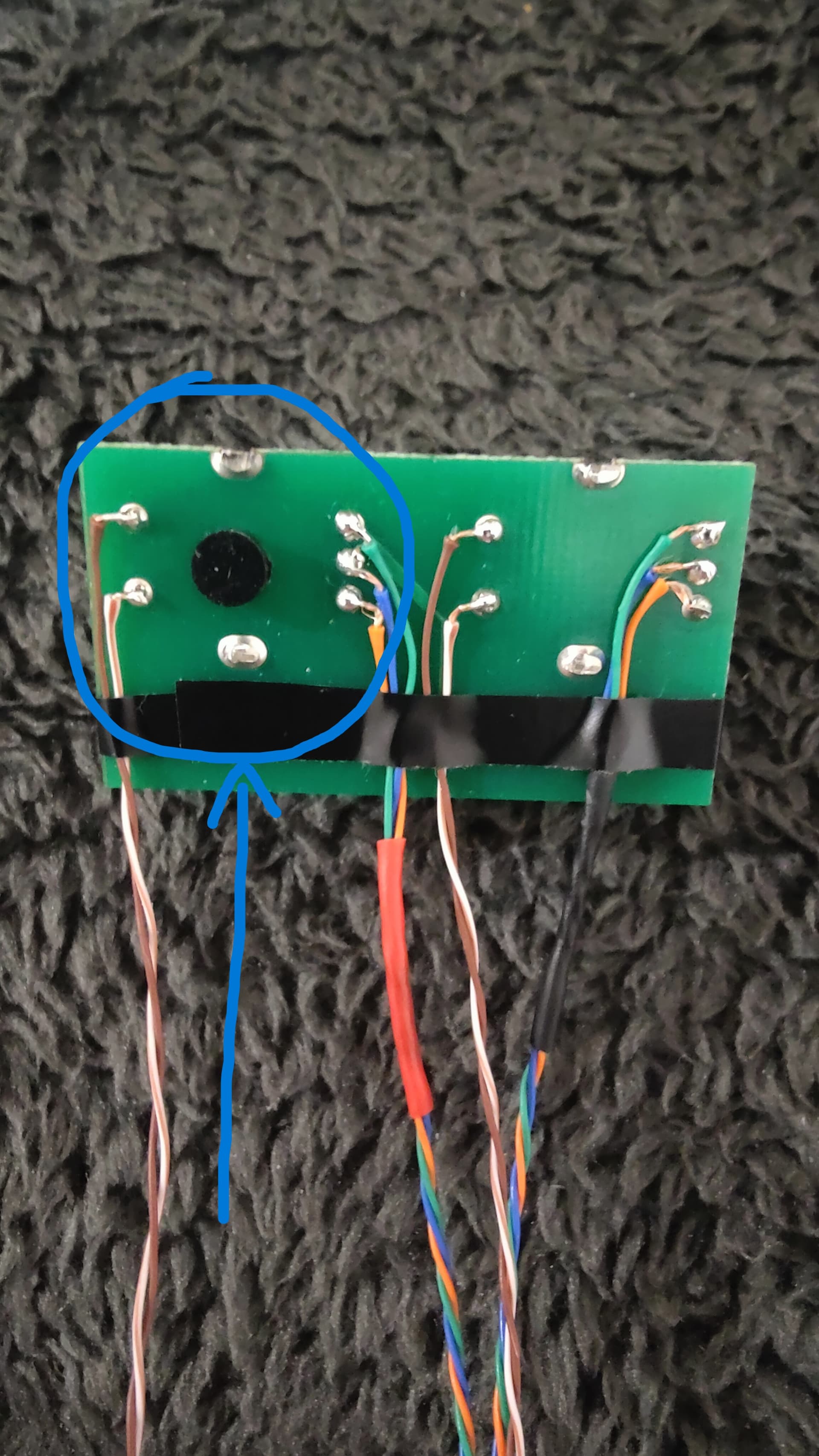
Ignore the other side of the board unless you want the DRUMSET knob function to be duplicated as well. (The procedure is exactly same for this, as you can see I have soldered another set of wires on additional 5pins on the right side.) I may or may not need/use this function remotely in future. Just prepared it whilst I was on it.
Keep the newly connected 5 wires length long enough to make further connections (Approx. 15cm each)
-
Now carefully assemble back all the board and connections in reverse order allowing the new wires out and to be able to be connected to further connections.
-
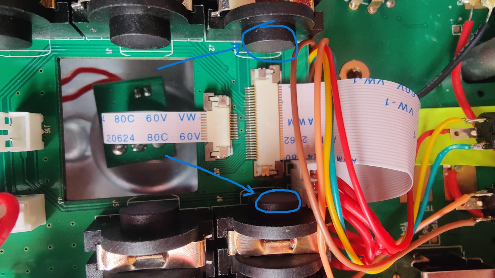
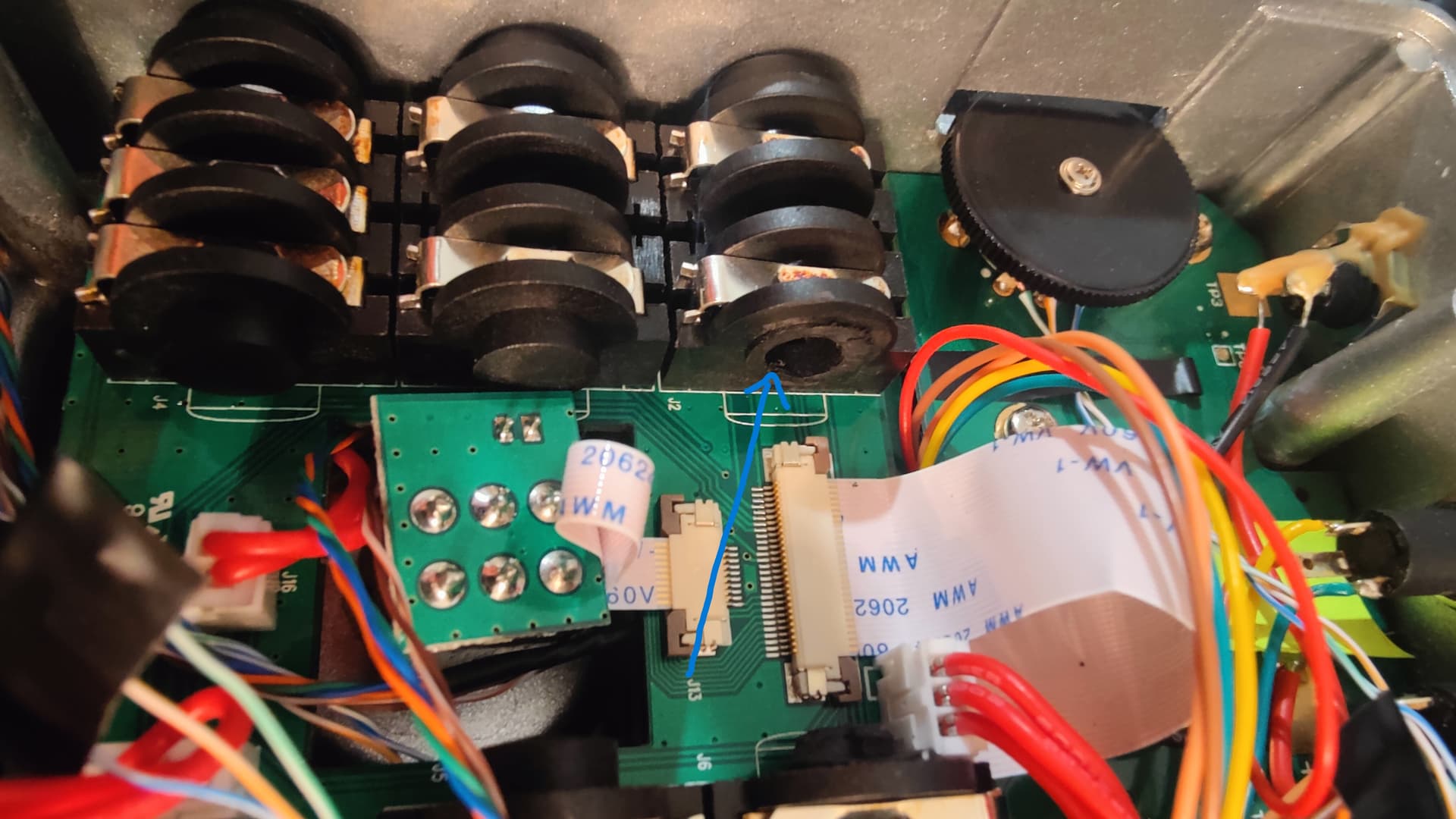
Now there is 2 ways we can take these wiring connections out of the Beatbuddy chassis itself for external connection.
A. Drill a hole on the pedal where you think will have enough room for connector mount and connect these wires to the mount.
OR…
B. You can do the way how I did using the existing Right input port. For this you will have to cut and trim the internal end of the R input port to make a hole for the USB cable to pass through. I used Dremel circular disc cutter which took only about couple of minutes.
Also, Please NOTE, with this option, you will lose stereo input feature but this is totally reversible, we are not losing any feature permanently. Also there’s always option A.
As you can see in the photos that I have prepared the R-Output side also for more connections if needed. Pic 10 Pic 11 Pic 12 Pic 13
-
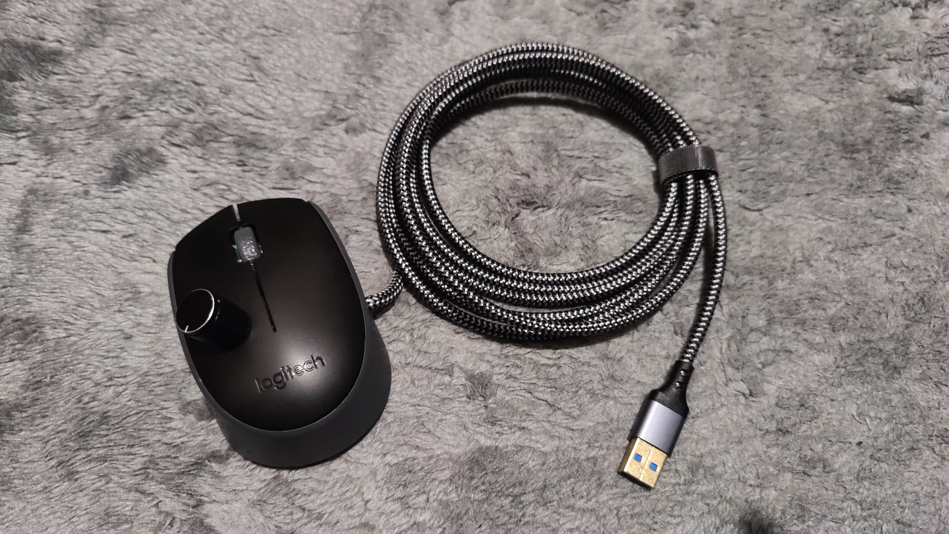
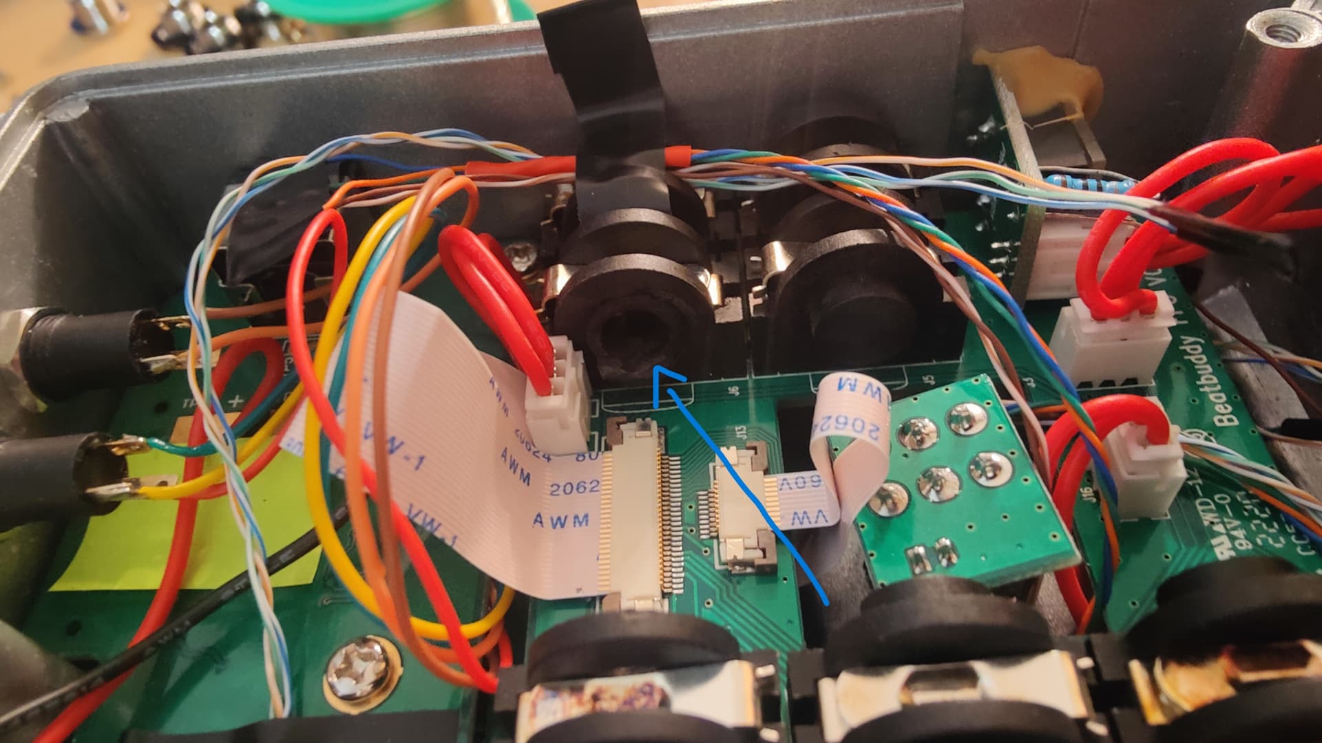
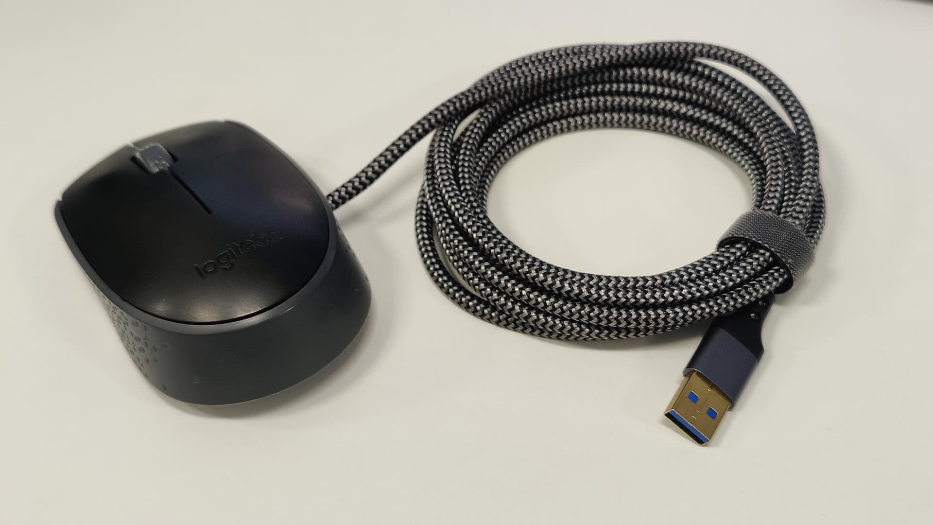
Then, I used a 3meter USB 3.0 extension cable which is easily available and does the job. The extension cable has male USB on one end and Female USB on the other end.
(using USB 3.0 because it has 9 individual wires we can make use of.
We only need 5 wires for this hack but I will be adding volume control too which will require 3 more wires that I have prepared already as shown in the photos. . Pic 14 Pic 15
-
Now Cut the USB cable on (female side) leaving about 15-20cm long. And insert the cut end through the R-input port now that it passes through with no issue. Pic 16
Then we connect previously prepared 5 wires (coming from the control knob) to any 5 wires of the USB cable. Please Keep the long-cut other end of the cable (Male side). We will utilize this cable to make the mouse connection.
15. Now the Beatbuddy back panel can be put back on. Pic 17
-
Whilst making connections to Mouse switches, you’ll have to wipe PCB connections that connects the mouse roller encoder or the click switches to any other components around them. I used Dremel again for this purpose. Pic 18 Pic 19 Pic 20
-
Please refer to wiring diagram for the mouse or any wired control box you choose to make your own extension control unit. Pic 21
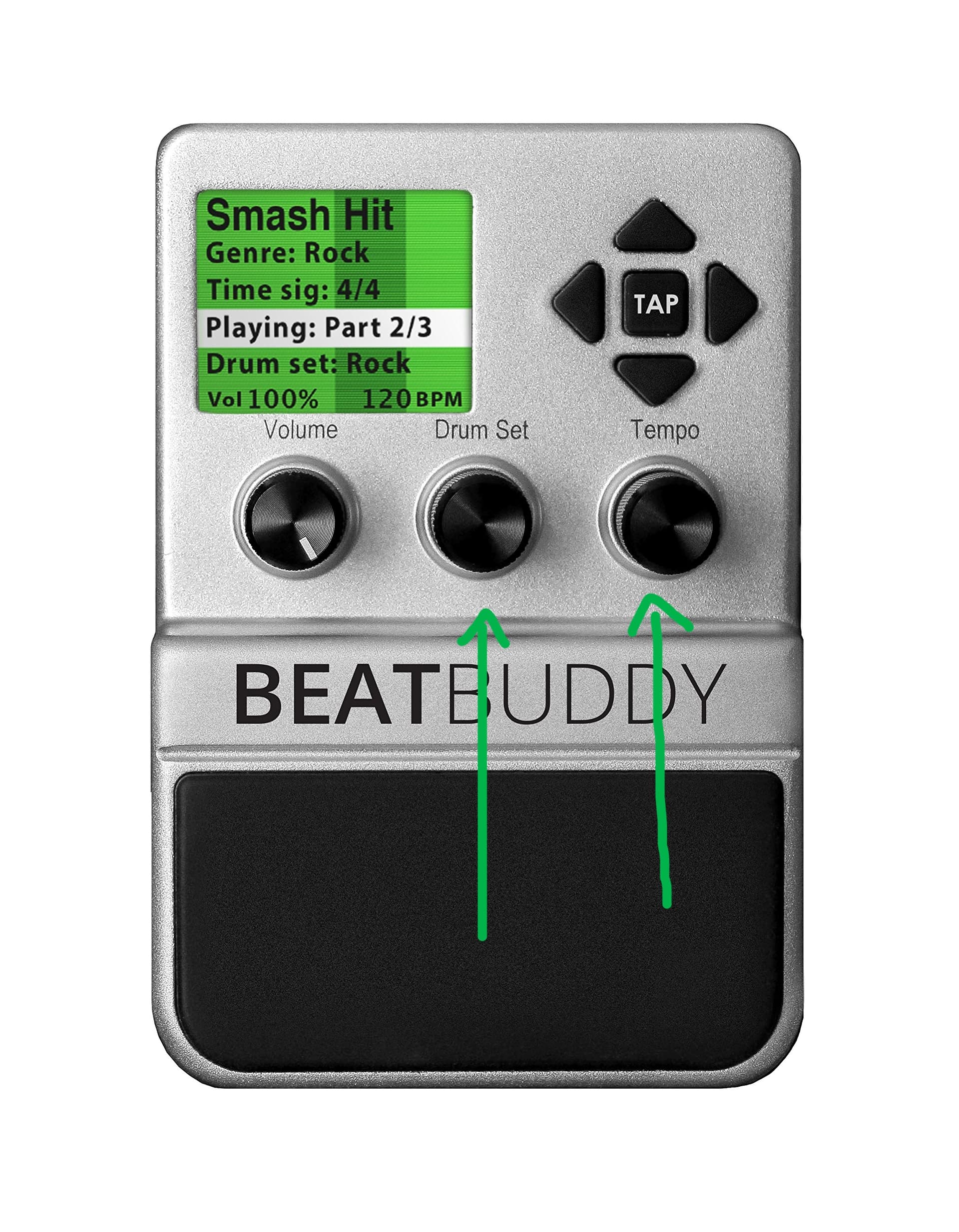
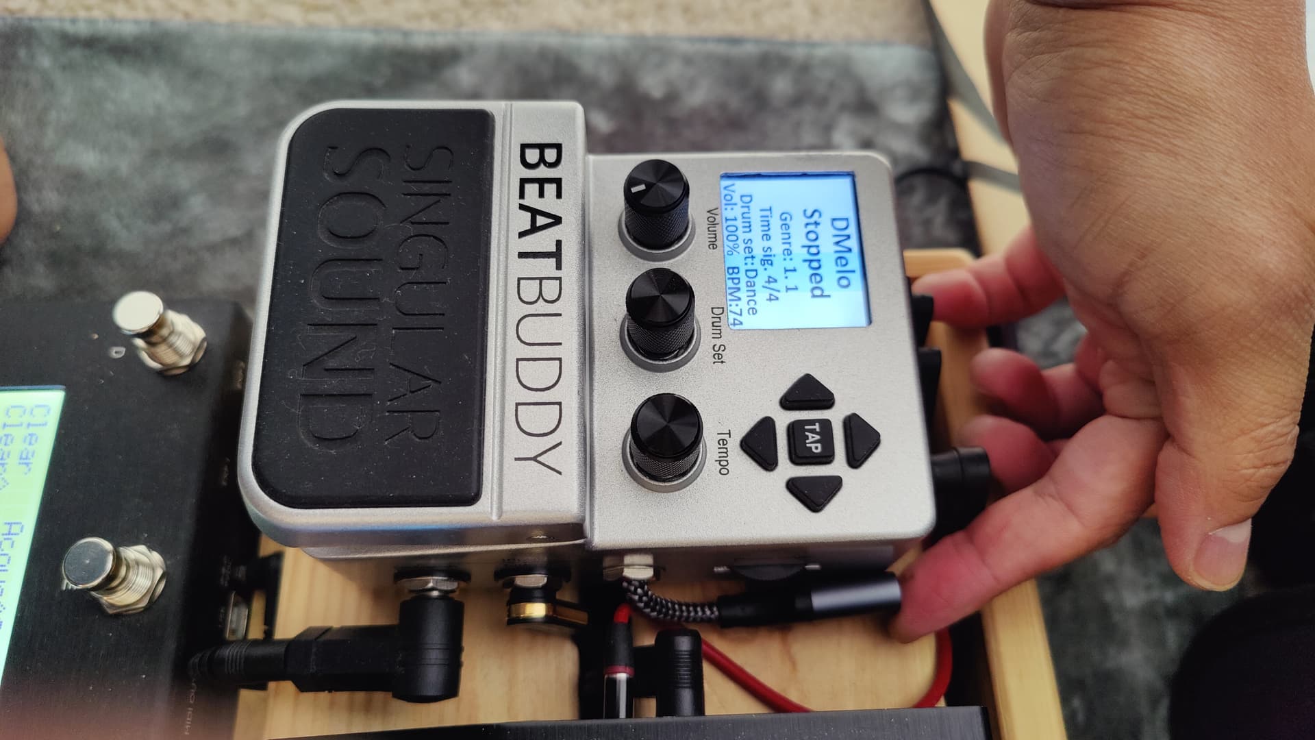
-
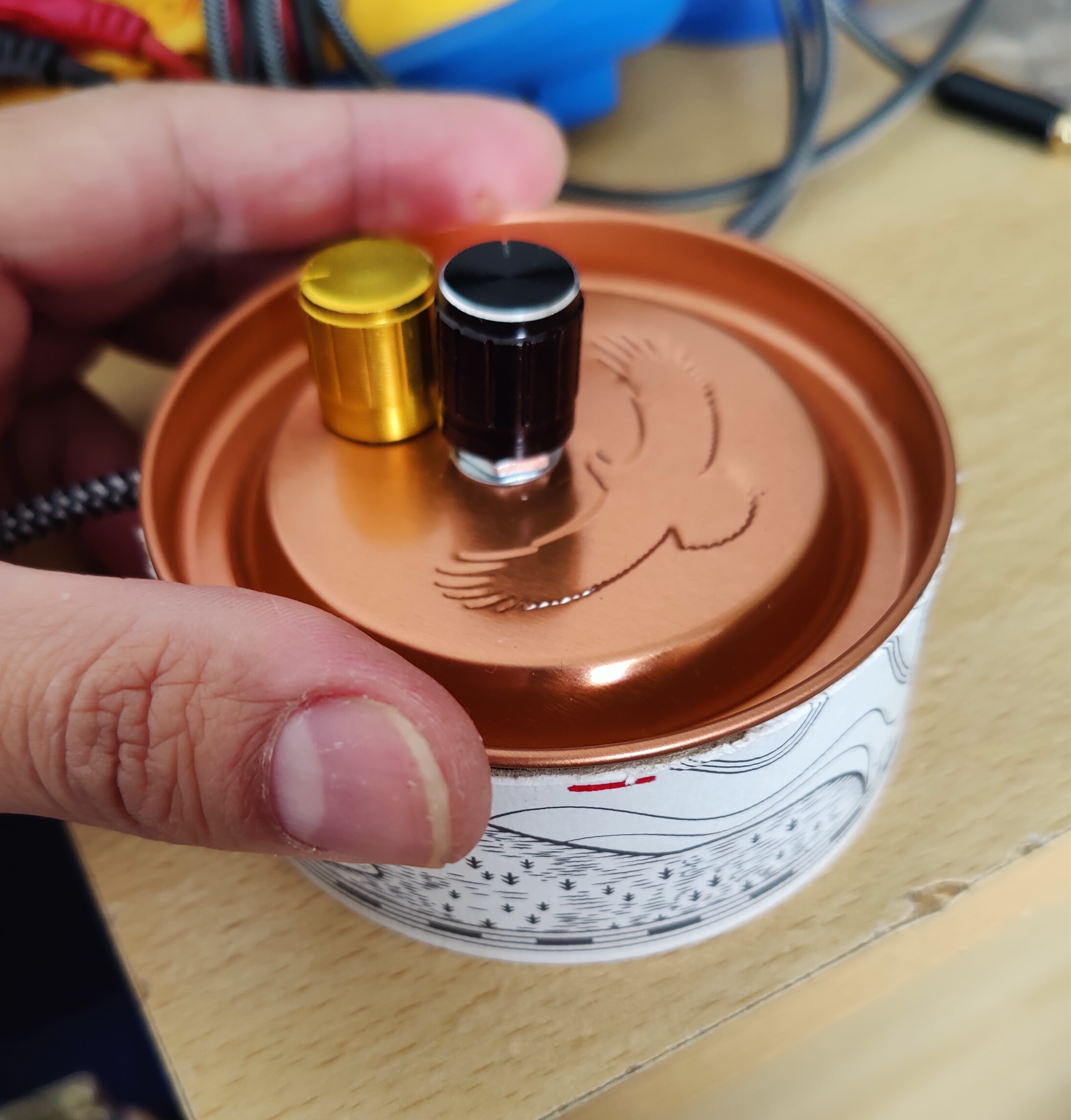
With these connections any box can be made to control using a Rotary Encoder and a potentiometer for volume control. Here’s an example with a volume Control added next to Main control knob. Pic 22
Please share your thoughts.
And also share your outcome if you make one.
Find me on
youtube: @uneel061
tiktok: @plusminus167
Song played in the background: