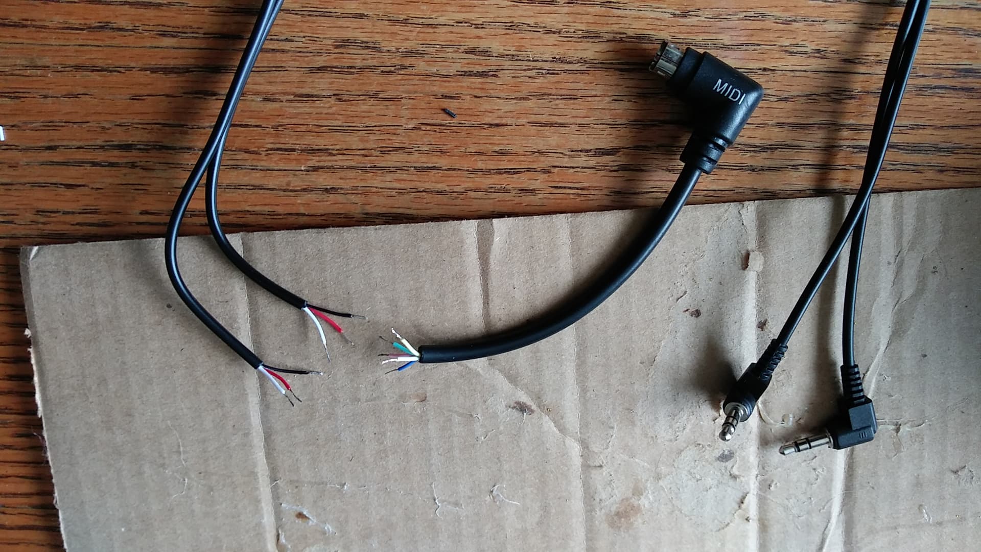
I am getting so confused, because all I can find are instructions on how to connect to the solder side of regular 5 pin midi connectors. All I want to do, is this!! (See pic) Which color wires go to tip/ring/sleeve? I know which wires go to which pins, and which are in/out. But I don’t know much about midi, and this rather proprietary cable/connector isn’t making this as easy as I thought it would be. Can someone just tell me which color wires go to tip/ring/sleeve? I know this is possible, because I’ve seen the post where # Nepali_brother did this, but I am confused!!! 
Alright, so with the help of Nepali_brother (Thanks man!  ), I think this is what you should include in the manual. I haven’t soldered this together yet, because I got too frustrated trying to figure it out earlier, with the lack of specific info. But, this should be correct. (And do correct me, if this is wrong!) This should make it pretty foolproof, for others.
  I’ll let you know how this works, when I solder it together tomorrow. Or maybe later tonight. My frustration level was pretty high.
TRS:
tip - red
ring - white
sleeve - black
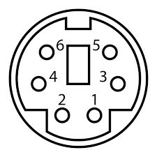
PS2 Mini Din:
#1 = blue out to red TRS
#2 = green out to white TRS
#6 = yellow out to black TRS
#3 = white in to red TRS
#4 = pink in to white TRS
#5 = N/A
Black/sleeve is not used on in TRS
According to the pinout, as in this image.
[Edited: Oops! I accidentally listed black twice on the outs!]
1 Like
Correction required here mate:
#1 = blue out to red TRS
1 Like
Thanks for that!! I accidentally listed black TRS twice on the out, but I had it right in my notes. It’s been corrected.  I still haven’t gotten it done yet. I had a dentist appt, and some other shit to do.
1 Like
No problem mate
1 Like