Replacing BeatBuddy Mini DIN Socket with TRS Midi

Probably my warranty was done but it was worth it. I used TRS Type A standard. For type B you have to make the necessary adjustments.

  1. You need 5 wires, two 6,5 TRS sockets, a driller to make the holes and a soldering iron.
  2. I disassembled the printed circuit board where the Mini Dinconnector is soldered.
    For that you have to remove the backplate, the phones potentiometer wheel and 3 screws.
    To identify the soldering points in the printed circuit I connected two Midi Cables to the Midi Sync cable IN and Out and tested where pins 2,4 and 5 were connected using a multimeter. I made a drawing of resulting scheme. The points 1-6 are the soldering points of the Midi Din connector.
  3. Make the holes on the Beatbuddy Box. You have to be carefull on chosing TRS stereo connectors that are small enough for the space you have and protecting the interior so that the aluminum pieces do not float inside
  4. I did not remove the old socket so I have a backup connection in case of a connection problem with the new ones. Connect points 5 and 2 to Tip and Ring of Midi In socket (no need to connect Ground). Connect points 4, 3 and 1 to Tip, Ring and Ground of Midi Out socket.
  5. Reassemble the printed board into place, fix the new sockets into its place and the backplate. Thats it.

Hope this helps others to make this improvment on this allready excelent piece of hardware

8 Likes

Great idea. Thanks for posting the pictures and schematic

My pleasure :slightly_smiling_face:

Very impressive. I am thinking of mounting 3.5mm sockets on mine.
Thank you for the schematic.

3.5mm sockets would be easier to accommodate in the space. My option for 6.5 was just because my Midi Controler has this type of connectors. Go ahead and share your experience here.

1 Like

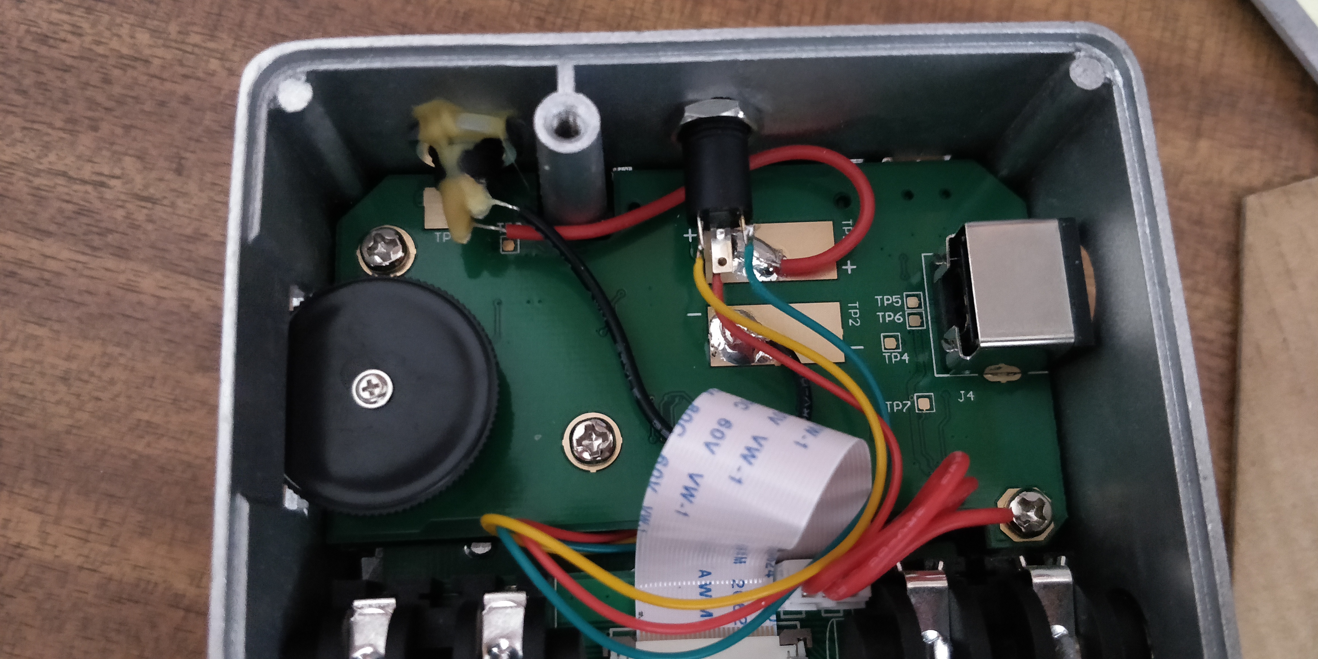
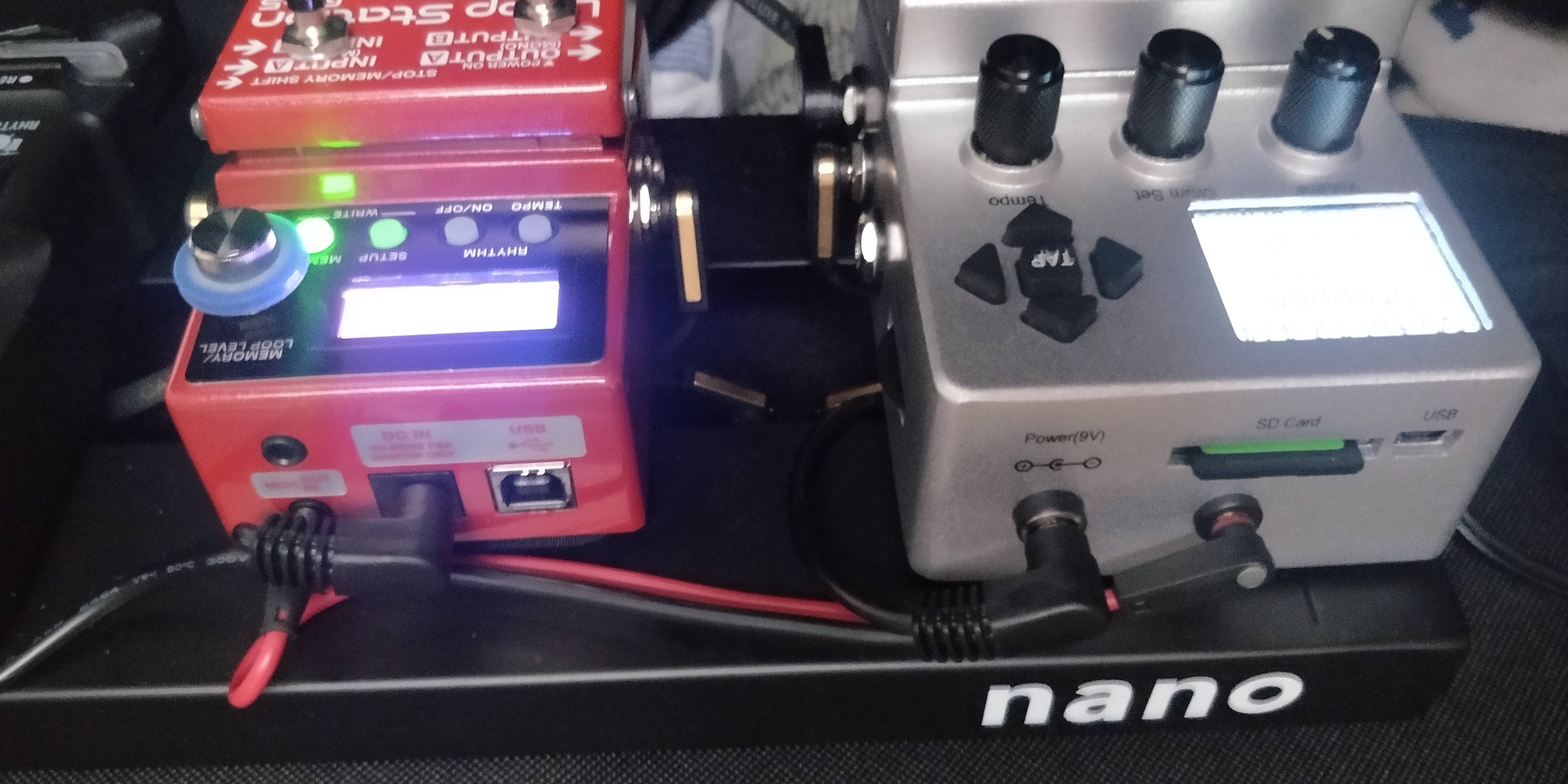
Finally modded (home DIY) mine with a 3.5mm trs connector for midi. I always use BB as master so only needed BB midi out. Thank you @XBeat for the great idea. I love this forum.
Cheers

6 Likes

Nice job @Nepali_brother. THe photo of PCB with the soldering points is very important. I didn’t post one because when I decided to make this thread I already had everithing remounted. Good beats man!

1 Like

As much as I fear modding a pedal, I really hate the prone to disconnect mini din connector.

Rear mounted jack is a nice benefit at well.

1 Like

One day all Midi’s will be TRS…

My OCD would not let me sleep before installing a second one.

3 Likes

have a good night’s sleep :sleeping:

1 Like

:+1::+1:

4 posts were split to a new topic: Can I replace a BeatBuddy surface mounted inductor?

Hello,
Thank you for the photos and comments.
On the diagram it is a back of the connections?
Sorry, if there are any mistakes, but I go through a translator because I am French
Many thanks in advance

Whoops !!
On the diagram is a rear view of the connections?
Sorry, if there are any mistakes, but I go through a translator because I am French
Thank you

Hello @Saxodany
What I’ve made was connecting a midi cable Male-Male to the the adapter from Singular Sound. Then I tested the connections between the printed circuit and the end of midi cable. So the answer is, the diagram is the view from the front.
Anyway, you just have to be concerned that you connect T to the tip, R to the ring and G to ground of your stereo jack. Hope this helps you. If not, please insist.

Good evening, it’s super nice to help me. But I don’t understand something, on the BB there is only one PS / 2 output (midi connection). But on your diagram there are 2 x PS / 2? On the other hand, if you understand correctly in the diagram the PS / 2 sockets are not presented on the soldering side? Thanks again

On the diagram I did not represented the PS/2 socket. Instead, I connected the Singular Sound Beatbuddy Midisync cable that makes the conversion from PS/2 to 2 x Din 5-pin and mapped the points in printed circuit (where the PS/2 socket is soldered) directly to the two Din 5-pin Midi In and Out. In fact that scheme was just to identify the current source (pin 4), shield (pin 2) and data (pin 5)
image
That was the only information you needed If you wanted to install standard Din 5-pin sockets in the Bestbuddy box (I think thats impossible due to lack of space).
In fact I wanted to install TRS Type A connection as used by Boss, Line 6, Korg and IK Multimedia. For that I used the conversion from pins to TRS plug 5-Tip, 4-Ring and 2-Sleeve as you can see in following image
image
I did draw the rear view of my TRS sockets on the right side of the scheme identifying the solder points with T-Tip, R-Ring and G-Ground/Shield. Of course, TRS sockets from diferent manufacturers may look diferent. You may have to find the correct solder points for tip, ring and shield by yourself.

great thanks a lot. But my BB is still on warranty that’s why I wanted to make my PS / 2 and 2 x TRS (RC-5 side).
I put my first cable attempt that I have to redo.
Do I have to buy a BB midi cable?
knowing that I already have all the connections to solder.


Please refer to this connection…