Hi all,
just sharing this little DIY hack if you use midi connection between BB and boss devices with TRS midi in/out.
Initially I bought both cables;
- BB midi breakout cable,
- 5pin midi din to trs from Boss.
They did work; but something was bugging me.
I ended up with the long cable mess and big midi connections which took extra space and also added extra weight to the pedalboard.
I checked everywhere on the net for a simple solution to this but it never existed. so I thought of this hack in my mind.
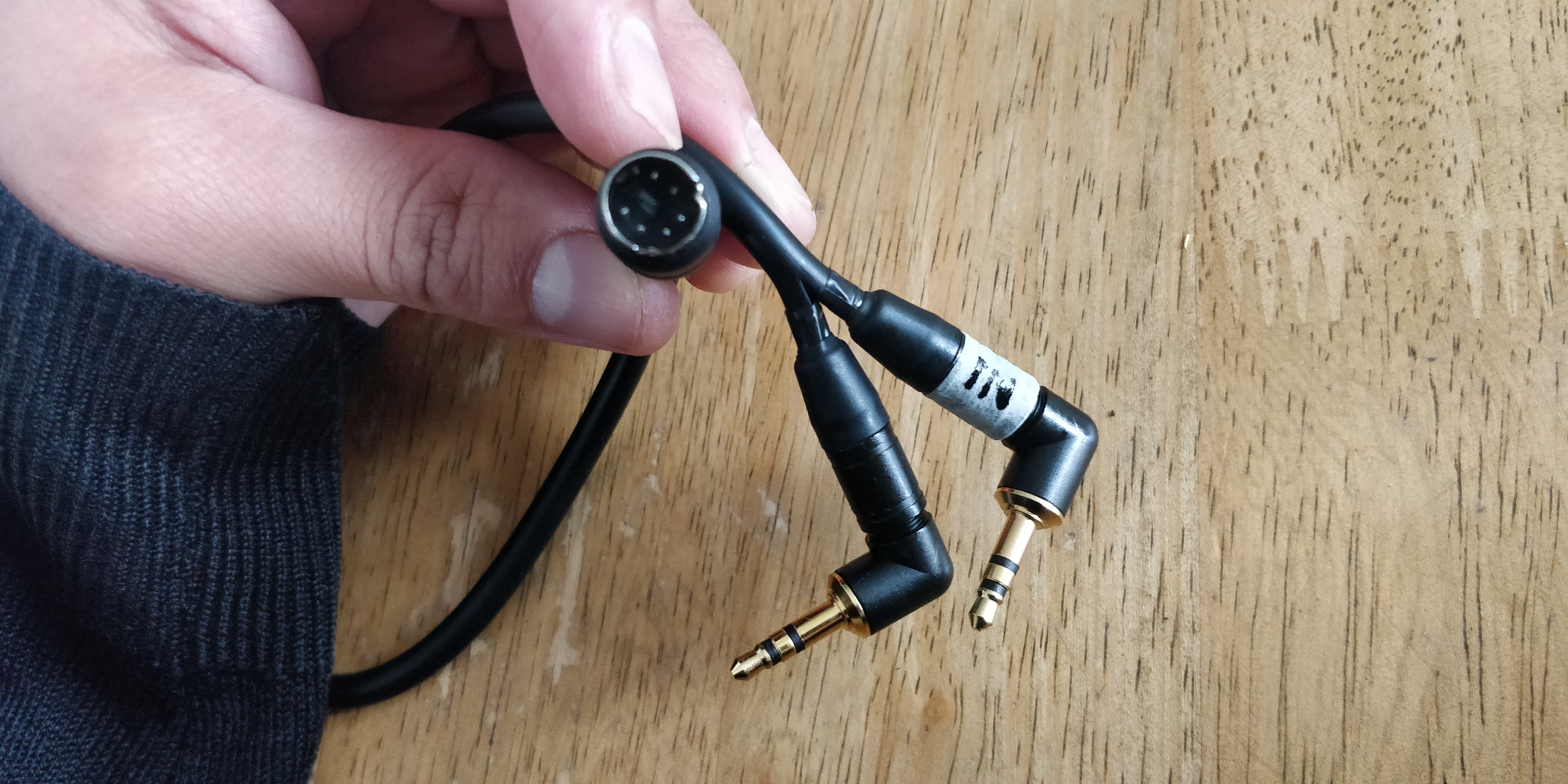
So I bought a PS/2 connection cable for less than £3 (amazon) and couple of good TRS connection plugs for £10 (amazon) and soldered them configuring the proper wire connections.
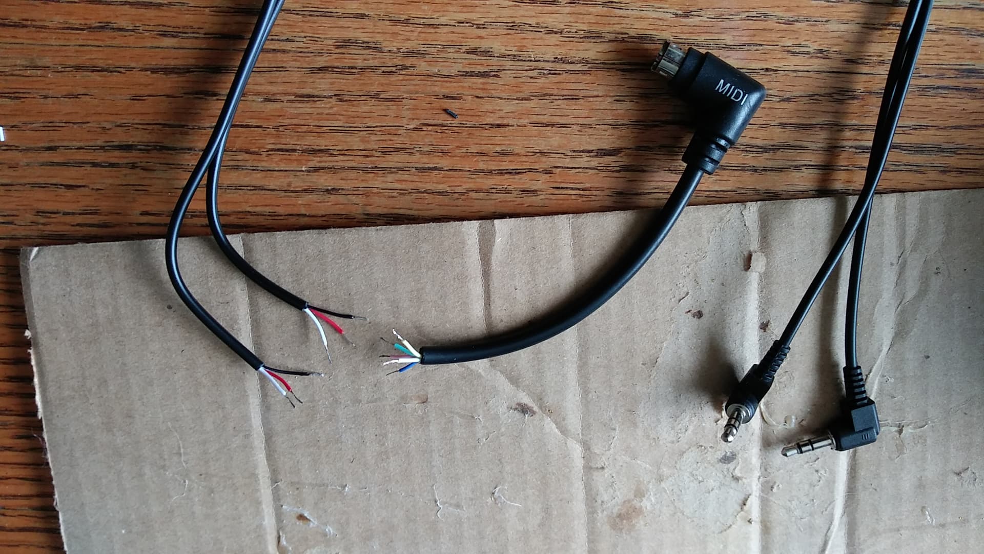
The DIY cable is very light and takes no space at all in the pedalboard. And yes it works like a charm.
Here is the photo of my cable.
peace.
7 Likes
Hello,
Thank you for the photos and comments.
I am new to the world of B.B and I am completely lost, but I am a good handyman.
I have a B.B and
an RC-5, I have already made a midi cable and
2 x 3.5 mm jack but it does not work
but above all I do not know how to make it work.
Do you have the wiring diagram please? and an explanation to test the cable?
Sorry, if there are any mistakes, but I go through a translator because I am French
Many thanks in advance
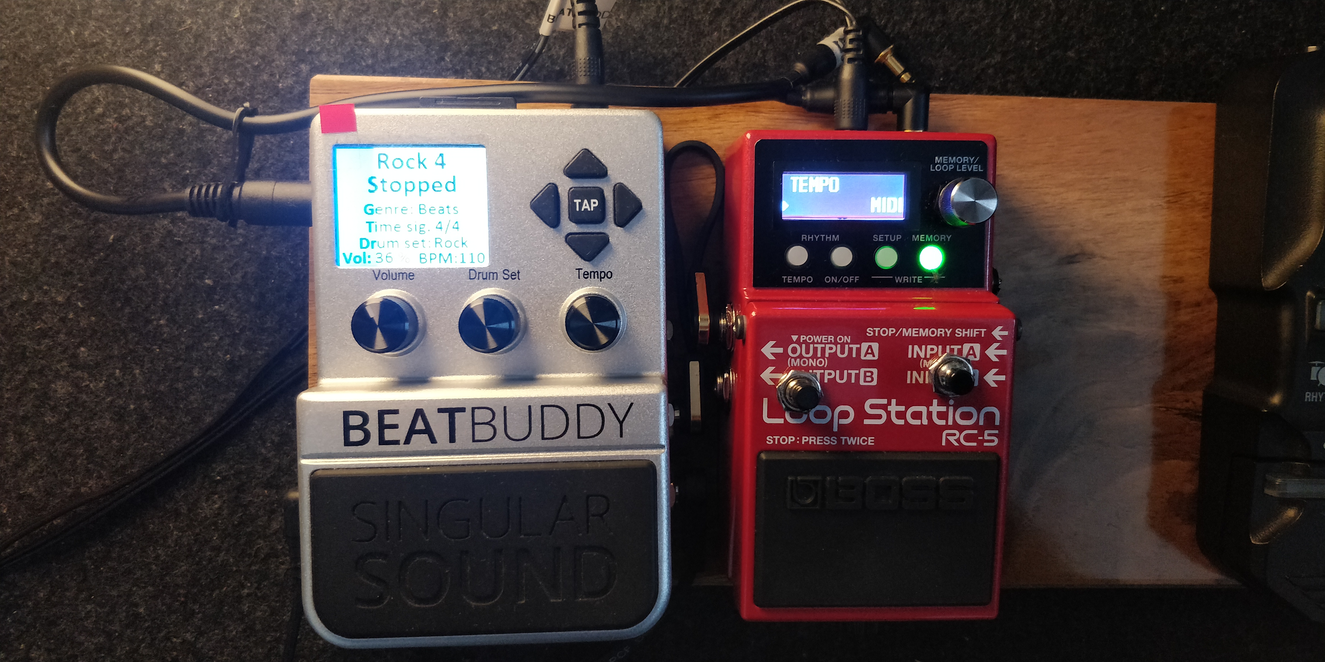
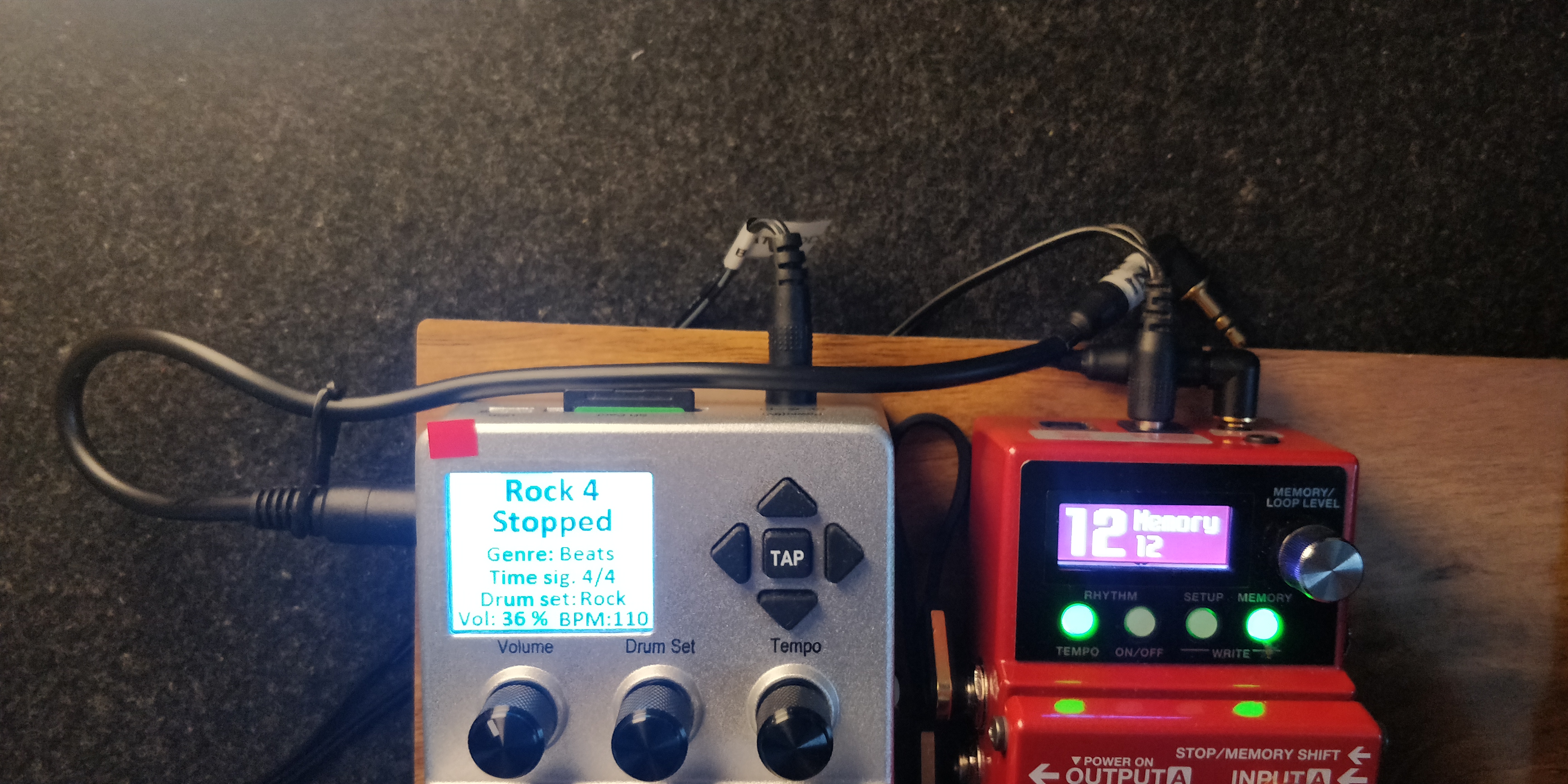
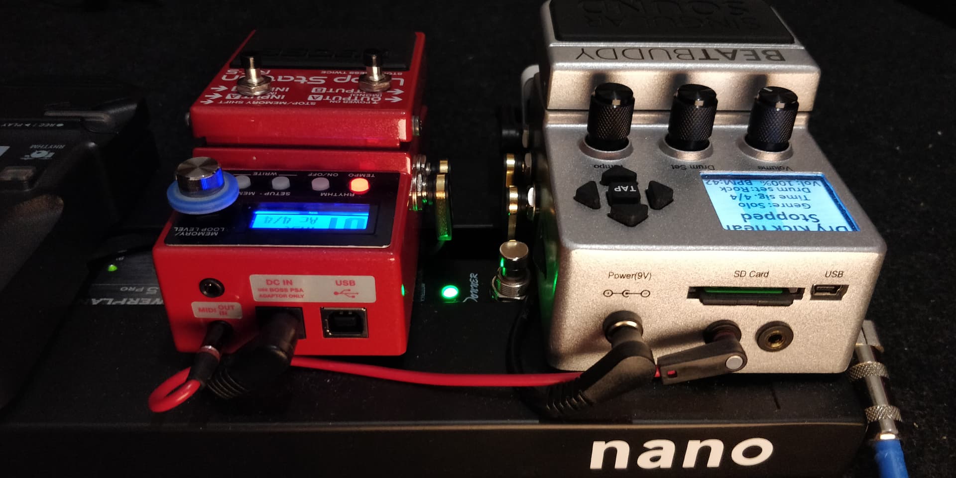
This is how i connect them now after 3.5mm jacks modification… For BB master and RC5 slave…BB “OUT” goes to RC5 “IN”. And vice versa.
Additional info below
1 Like
Great work, it’s impressive.
Did you remove the PS / 2 plug from the BB?
But as I want to act only on the PS / 2 midi socket of the BB (because of the warranty), I will see that.
I see in the photo that the RC-5 is Hiii DIY.
Thank you for all this info.
The ps2 still exists on my BB and it still works. You can do the cable hack refering to the same connection information shown above. I would avoid the BB modification and save the warranty if your BB is still new.
Yes, I have modded the RC5 aswell with additional two switches on the pedal itself. they operate as external footswitches and are assignable. Works great.
This is exactly what I am trying to do!! I am not sure I understand your diagram, because as far as I can tell, pin 5 is not even used. Can you just tell me which color wires go to R/T/S? I am really confused, here. 
See where I am on this? I just need to know which order to solder the wires. I feel like a dumbass. I don’t know anything about midi, really. Can you help?
Hi @SloppyGoat sorry i did not take note of wiring colour code because different make/brand cables may have different colour coding so it would not be relevant.
I would suggest you using multimetre to figure out which pin is connected to which coloured wire. And please refer to the connection shown in the photo on 3/7 post above.
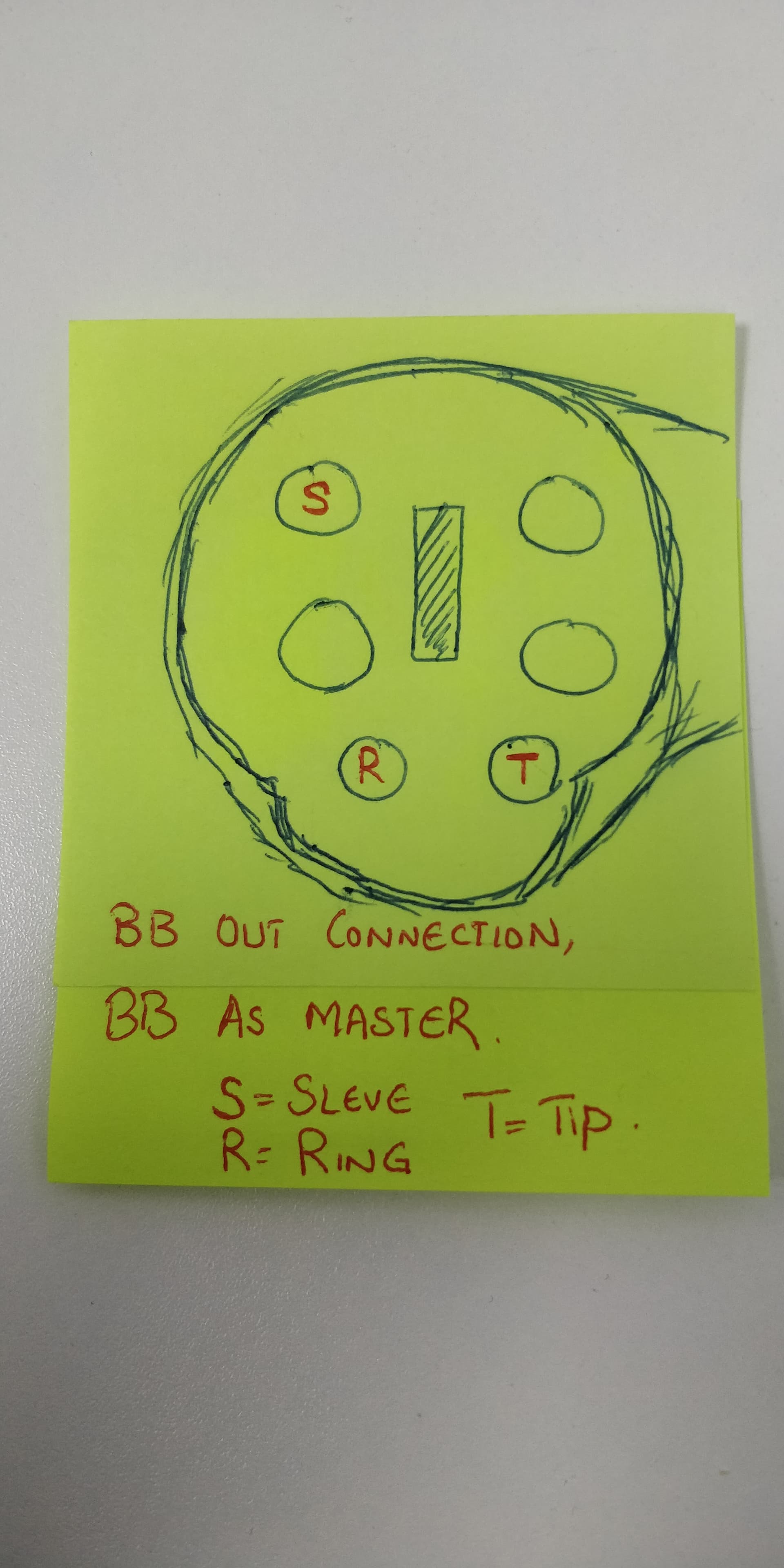
Ps. The (BB Out) connection for BB to be master is all we need.
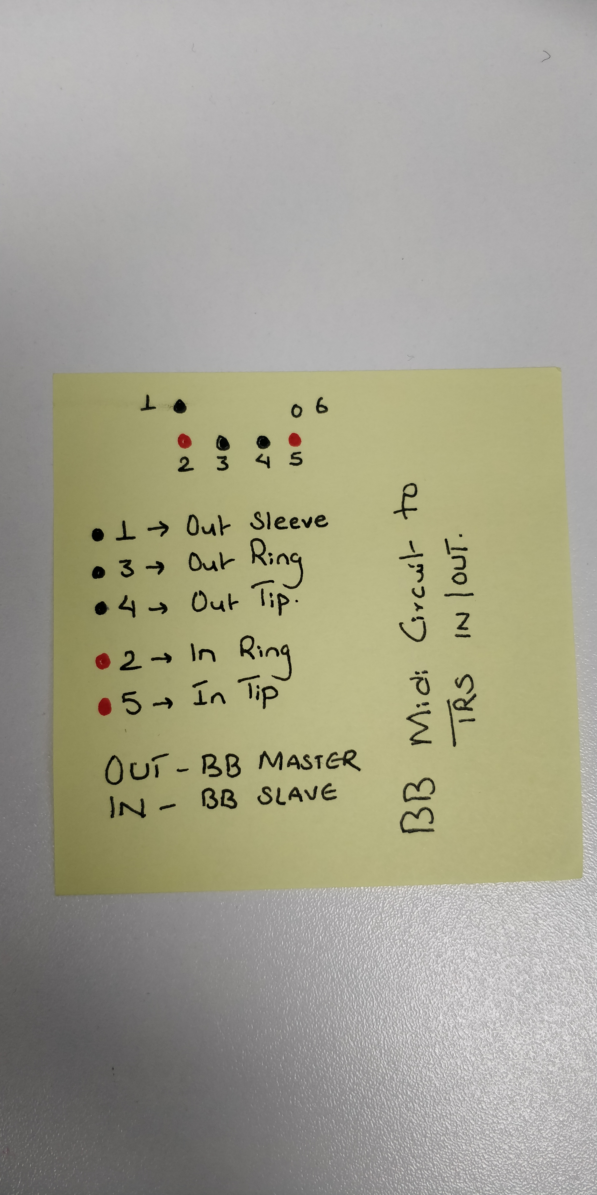
If you observe the diagram, Pin 1, 3 and 4 is all you need and link them to one TRS jack accordingly.
So the connection will be---- Pin 1 to Sleeve, Pin 3 to Ring and Pin 4 to Tip.
The prepared TRS jack will have to be connected to IN port of your looper.
That makes the BB master and your looper slave.
If you need more help please feel free to ask.
1 Like
Ok, that helps a bit. Because then, there are only two wires left for the in side. As long as I get the out TRS right, then the in side shouldn’t be that hard to figure out, I guess? I did already pin them out with a meter and write down which pins go to which colors. But then I got confused, when it didn’t work. You have to turn on midi out, on the RC-5, right? Maybe I had not done that, yet. AAARRRRGGGGHHH!!! This is such a simple thing, so I’m really feeling stupid, right now.  I have never messed with midi, before, so this is completely new to me. And there just is not a wealth of specific info on this!
Wait a minute, this is what I get when I pinned it out. That doesn’t make sense, with this data. Is this somehow wrong?
Mini Din
#1 = blue out
#2 = green out
#6 = yellow out
#3 = white in
#4 = pink in
Ok here you go again. See if this pic helps you more…
2 Likes
Thanks man! Any idea what the other side would be? Because, I’m going to heat shrink this all together, and I’d like to make sure I have both in/out soldered correctly, even if the in side doesn’t matter, for this application.
1 Like
could you please make a diagram of how you have numbered your mini din pins.
Because midi pins can be numbered in many ways.
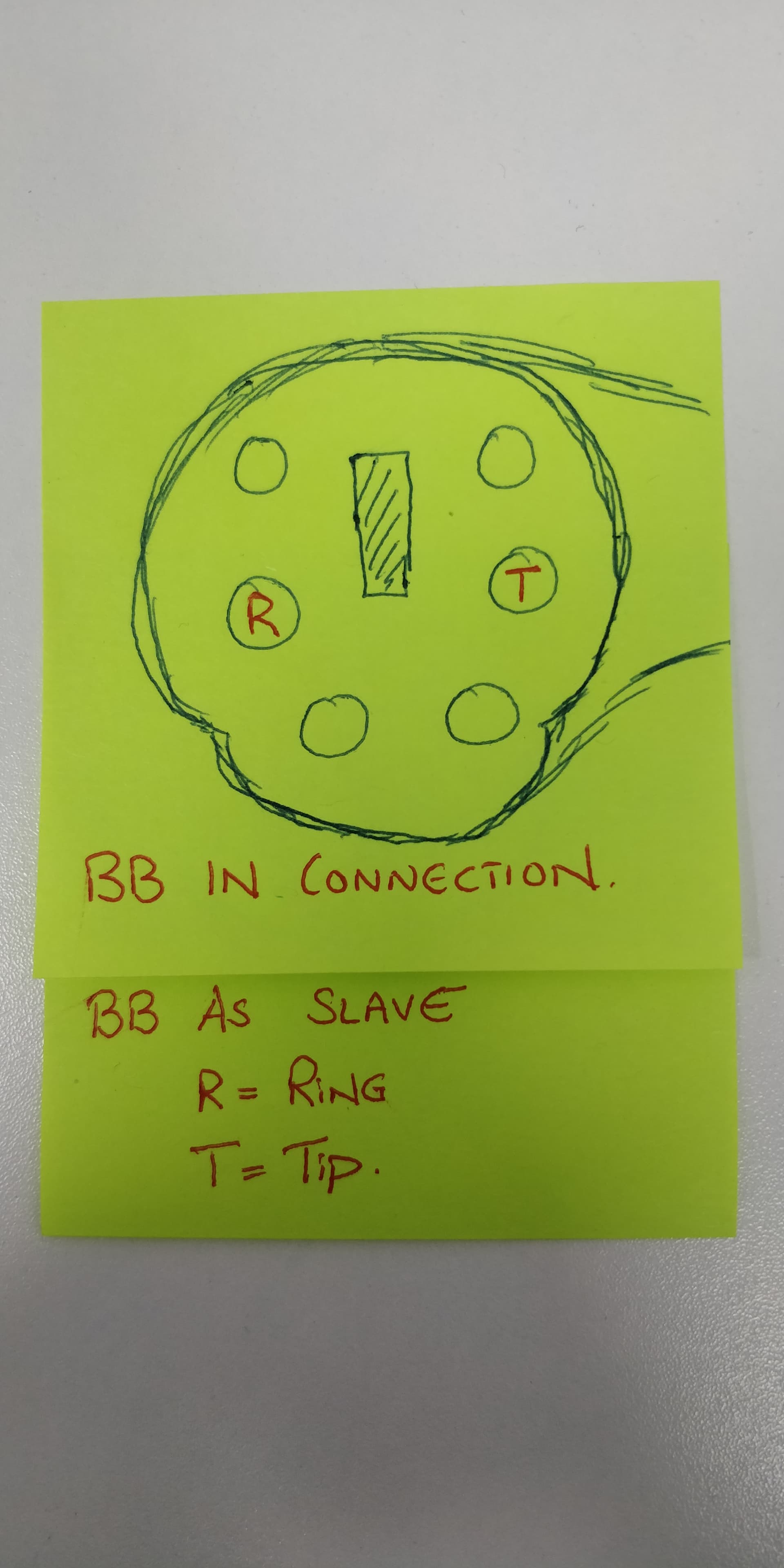
Ok. This pic below is for BB IN, BB as slave connection. Your looper will be master. Also you can connect midi controller devices to control BB.
Here you go…
2 Likes
Sweet!!! Perfect!!! Thank you so much!!! Now, I can finish this, and end my frustration!!! 
1 Like
@SloppyGoat No problem mate.
Please share your experience once you accomplish this.
All the best.
1 Like
That is a face view of the plug, right? I found a lot of diagrams of the solder side, or the receptacle connectors, and that made it even more confusing. LOL
Yes. All the diagrams above refer to the face view of mini din. As in looking at the Ps2 in the 1st pic of 1st post above. No more confusion i guess.
If you ever plan to mod your pedal and install female aux connectors for midi in future, you may refer to the exact same diagram as in the 3rd post, pic shown above. .
Hello Nepali_brother,
Sorry I allow myself to come back now because I had health problems, on the wiring of the BB and the RC-5.
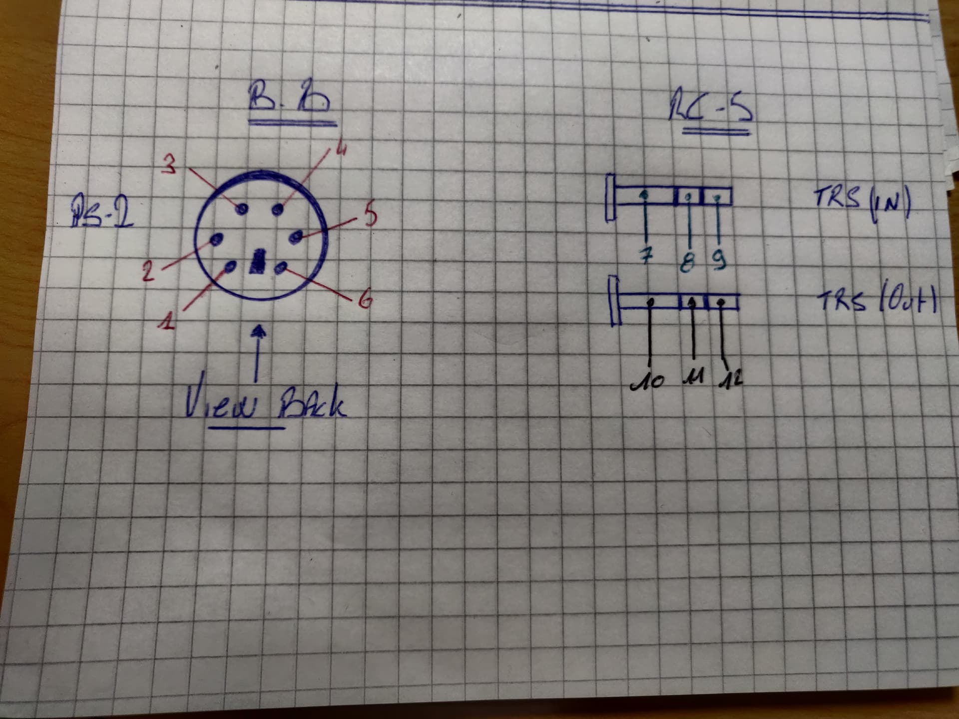
would it be possible to give me the identification according to my diagram. Because I have difficulty making my cable.
Many thanks
Hi @Saxodany i hope your health is all good now.
Before I suggest you anything, just wanted to confirm,
In your diagram, Are you showing the back of the ps2 connector for soldering?